Technical Appendix
SINUMERIK 802S base line
6-43
Start-Up
6.3.2 Input/output configuration
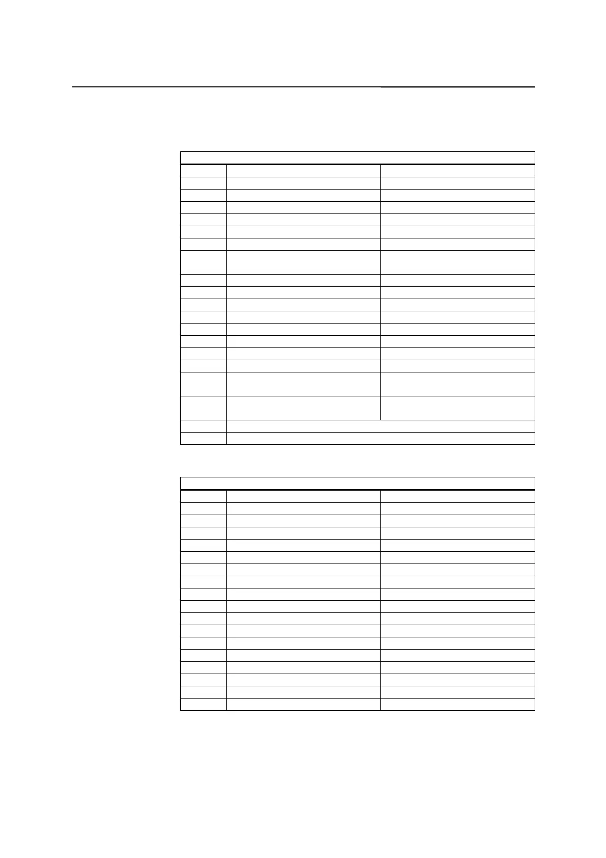
Input signals description
Input Signals Description
X100 For turning machine For milling machine
I0.0 Hardware limit X+ Hardware limit X+
I0.1 Hardware limit Z+ Hardware limit Z+
I0.2 X reference cam X reference cam
I0.3 Z reference cam Z reference cam
I0.4 Hardware limit X -
1)
Hardware limit X -
1)
I0.5 Hardware limit Z -
1)
Hardware limit Z -
1)
I0.6 Overload (T52 for 611 infeed
module)
Overload (T52 for 611 infeed
module)
I0.7 Emergency Stop key Emergency Stop key
X101
I1.0 Tool sensor T1 Spindle low gear in-position
I1.1 Tool sensor T2 Spindle high gear in-position
I1.2 Tool sensor T3 Hardware limit Y +
I1.3 Tool sensor T4 Y reference cam
I1.4 Tool sensor T5 Hardware limit Y -
1)
I1.5 Tool sensor T6 Not defined
I1.6 Over limit release for EMG
chain
Over limit release for EMG
chain
I1.7 Drive ready (T72 for 611U
infeed module)
Drive ready (T72 for 611U
infeed module)
X102 ~ X105
Not defined
Output signals description
Output Signals Description
X200 For turning machine For milling machine
Q0.0 Spindle CW
3)
Spindle CW
3)
Q0.1 Spindle CCW
3)
Spindle CCW
3)
Q0.2 Coolant control Coolant control
Q0.3 Lubrication control Lubrication control
Q0.4 Turret CW undefined
Q0.5 Turret CCW undefined
Q0.6 Chuck clamping Tool clamping
Q0.7 Chuck unclamping Tool release
X201
Q1.0 Undefined Spindle gear level low
Q1.1 Undefined Spindle gear level high
Q1.2 Undefined undefined
Q1.3 Motor brake release Motor brake release
Q1.4 Spindle brake Spindle brake
Q1.5 Supply infeed: T48 Supply infeed: T48
Q1.6 Supply infeed: T63 Supply infeed: T63
Q1.7 Supply infeed: T64 Supply infeed: T64

 Loading...


