Installing the STEPDRIVE
SINUMERIK 802S base line
3-3
Start-Up
3.2 Cabling
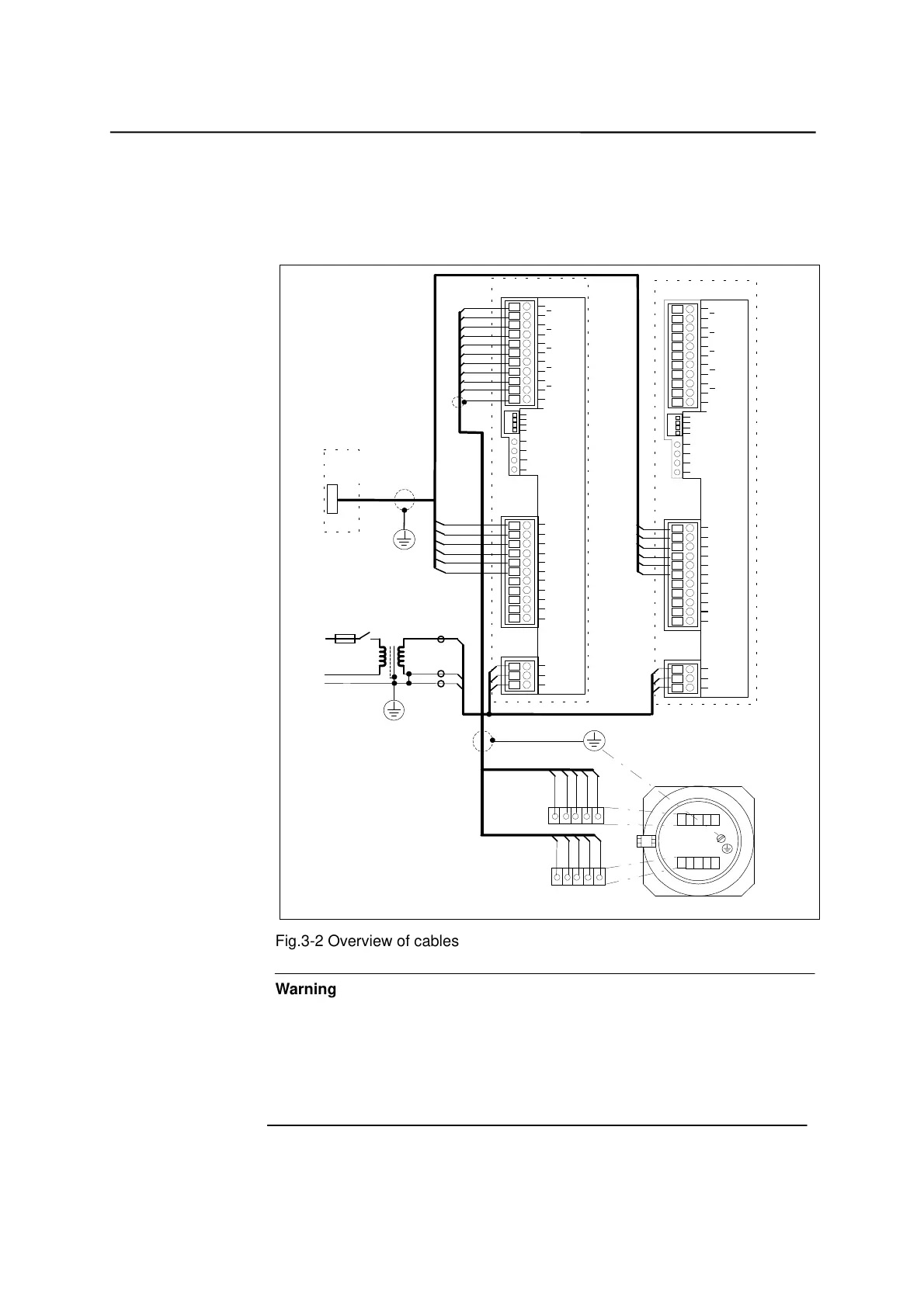
Cable overview
Connect the STEPDRIVE C/C+ drive modules, the BYG stepper motors and
the SINUMERIK 802S base line control system as shown in Fig. 3–2:
A
A
B
B
C
C
D
D
E
E
PE
RDY
TMP
FLT
DIS
CURR.1
CURR.2
RES.
DIR.
+PULS
-PULS
+DIR
-DIR
+ENA
-ENA
RDY
ZPH
+24V
24V GND
PE
L
N
PE
A
A
B
B
C
C
D
D
E
E
PE
RDY
TMP
FLT
DIS
CURR.1
CURR.2
RES.
DIR.
+PULS
-PULS
+DIR
-DIR
+ENA
-ENA
RDY
ZPH
+24V
24V GND
PE
L
N
PE
Drive of axis 1
Drive of axis 2
SINUMERIK 802S
base line
X7
Motor cable
yellow
white
blue
red
orange
green
gray
black
brown
purple
P1
P1N
D1
D1N
E1
E1N
P2
P2N
D2
D2N
E2
E2N
Motor connection anal. to axis 1
yellow
blue
white
red
orange
green
gray
black
brown
purple
Motor
230VAC
L
N
PE
230/85 VAC transformer
Qsfbt t fn cmfe dbcmf
7GY3113.4BE 13.2 yy1
Fig.3-2 Overview of cables
Warning
Prior to performing connection work, always first make sure that the supply
voltage is switched off.
With the supply voltage switched off, hazardous voltages are present at the
mains and motor connections. Under no circumstances may these connection
be touched in the ON condition; otherwise, loss of life or severe personal injury
could be the consequence.
!
Preassembled cable
6FX2002-3AD02-1xx0

 Loading...


