Technical Appendix
6-50
SINUMERIK 802S base line
Start-Up
6.3.5 SAMPLE program structure
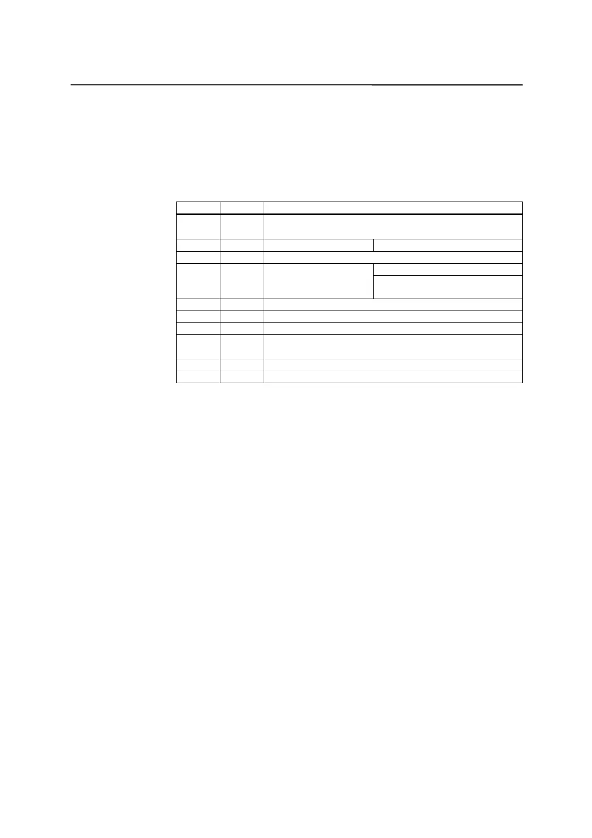
Definition of subroutine
In this SAMPLE program, the user can complile subroutines from 0 to 30, and
the function of the individual subroutine is described in the subroutine library.
See below.
MAIN (OB1)
Seq. # SBR # subroutines
162
Input & output signals filtering (IW0/QW0 →
MW100/MW102)
232
PLC initialization →
SBR31 – customer initialization
3 33 Emergency Stop
SBR34 – Traverse key control4 38 MCP signal process
→
SBR39 – Handwheel select via
HMI
5 40 XYZ and spindle enable/disable
6 44 Coolant control
7 45 Lubrication control
835
Contactor spindle or analog spindle (0~10V or ±10V
setpoint )
9 41 Turret control
10 49 Clamping and unclamping control
I/O signal processing
SAMPLE is designed to meet the different wiring on the machine tools, i.e. any
input can be connected as Normal Open, or Normal Close. All input and output
signals have been filtered by SBR62 FILTER. The I/O filtering is carried out
according to PLC MD14512[0], [1], [2], [3] and MD14512[4], [5], [6], [7].
Principle of I/O filter
with follow chart, it is easily know the correspondence of internal inputs and
outputs. Therefore in SAMPLE M100.0 is a buffered input for I0.0, and
M101.2 is for I1.2; M102.3 is for Q0.3 and M103.4 is for Q1.4, and so on. All
subroutines in LIBRARY are inputs/output independent.

 Loading...


