Technical Appendix
6-44
SINUMERIK 802S base line
Start-Up
Note:
1. Undefined when only a single hardware limit switch of each axis.
2. When a 4 position turret is used, I1.4 and I1.5 not defined;
3. When MD30134=1/2 , Q0.0 and Q0.1 can not be defined in PLC.
Meanwhile, Q0.0 and Q0.1 are defined as the direction of unipolar
spindle and enable signals which are controlled by NCK.
Notice
All input signals are treated in SAMPLE as Normal Open(or called positive
logic). If an input is a Normal Close, it should be specified via PLC MD as
negative logic.
Spindle enable signals come from P17(SE4.1) and P50(SE4.2) (Internal relay)
of X7.
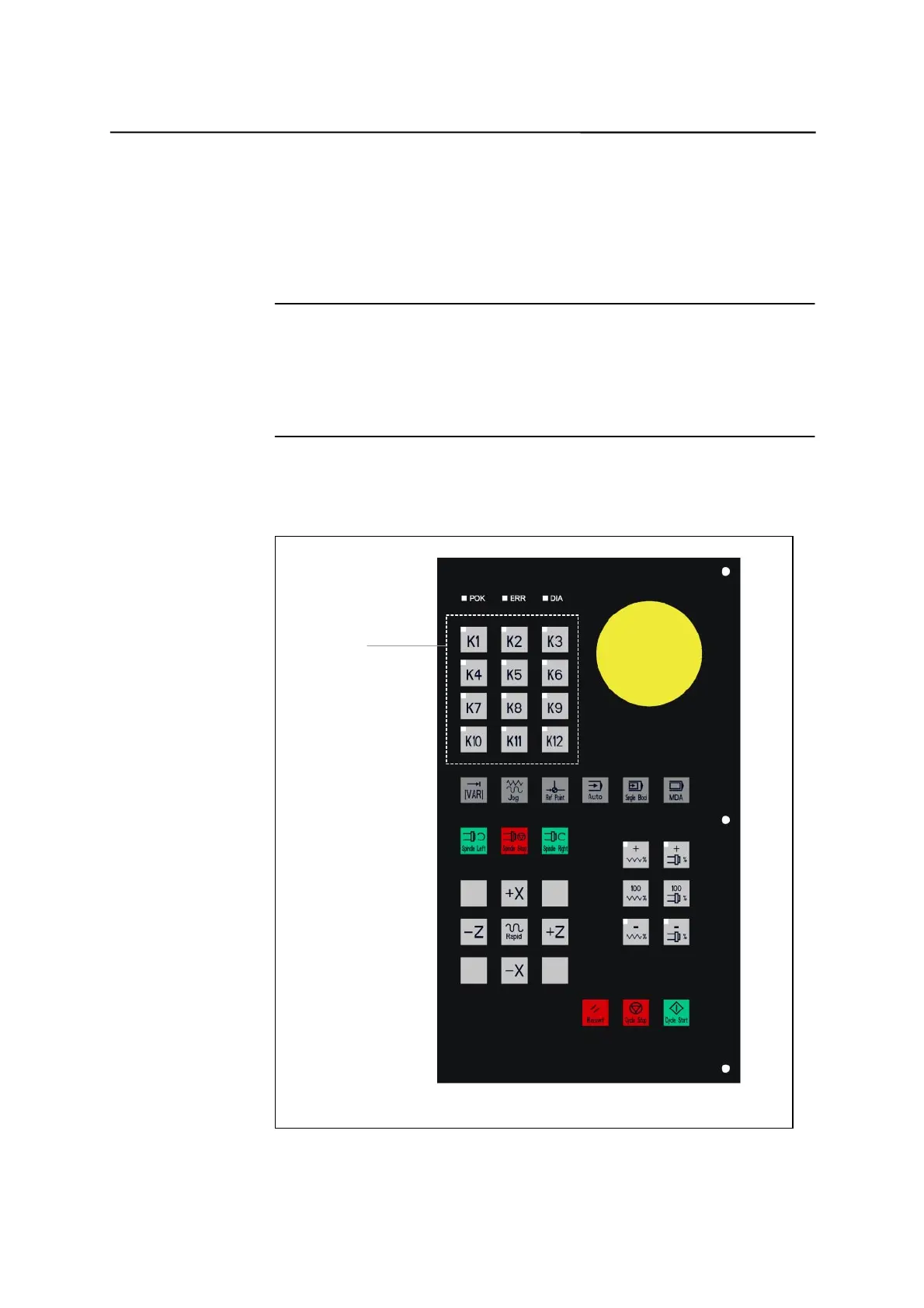
6.3.3 Definition of user keys
User keys
Fig. 6-1 User keys on MCP area
!

 Loading...


