Installing the Control System
SINUMERIK 802S base line
2-7
Start-Up
2.3 Connecting the individual components
Connecting the components
Please note the following:
Notice
Use only shielded cable and make sure that the shield is connected to the
metal or metal plated connector casing on the control side. For the purpose of
isolating the analog setpoint signal from low-frequency interference, we
recommend not to ground the shield on the drive side.
The preassembled cable offered as accessories provides optimum protection
against interference.
General procedure:
Proceed as follows to connect the individual components:
1. Connect the cables to the components as shown in Fig. 2–3.
2. Fix the sub-D connector in place using the knurled screws.
2.3.1 Connecting the feed drives and the spindle (X7)
Pin assignments For connector on the CNC side
Feed drive interface
Connector designation: X7
AXIS 1–4
Connector type: 50-pin sub-D plug connector
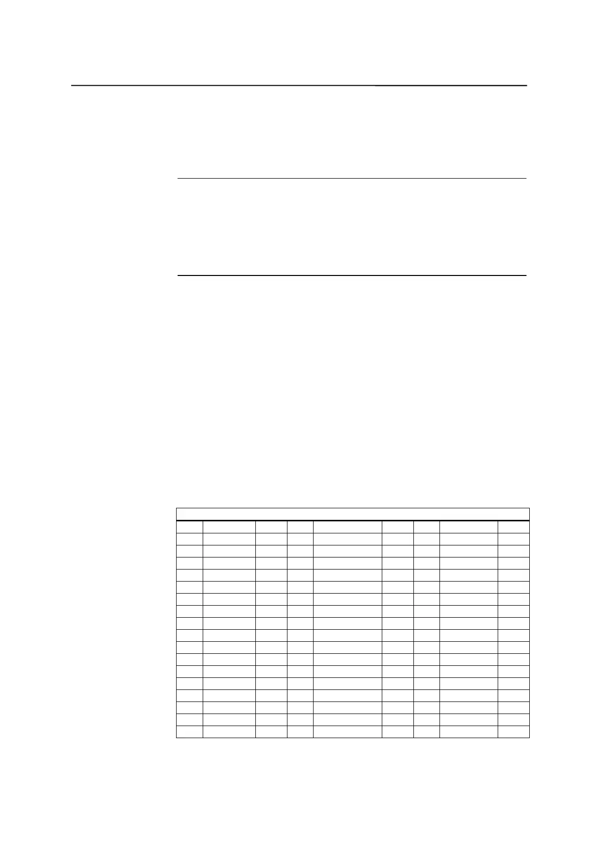
Table 2-1 Pin assignments of connector X7
X7
Pin Signal Type Pin Signal Type Pin Signal Type
1 n.c. 18 ENABLE1 O 34 n.c. AO
2 n.c. 19 ENABLE1_N O 35 n.c. AO
3 n.c. 20 ENABLE2 O 36 n.c. AO
4 AGND4 AO 21 ENABLE2_N O 37 AO4 AO
5 PULS1 O 22 M VO 38 PULS1_N O
6 DIR1 O 23 M VO 39 DIR1_N O
7 PULS2_N O 24 M VO 40 PULS2 O
8 DIR2_N O 25 M VO 41 DIR2 O
9 PULS3 O 26 ENABLE3 O 42 PULS3_N O
10 DIR3 O 27 ENABLE3_N O 43 DIR3_N O
11 PULS4_N O 28 ENABLE4 O 44 PULS4 O
12 DIR4_N O 29 ENABLE4_N O 45 DIR4 O
13 n.c. 30 n.c. 46 n.c.
14 n.c. 31 n.c. 47 n.c.
15 n.c. 32 n.c. 48 n.c.
16 n.c. 33 n.c. 49 n.c.
17 SE4.1 K 50 SE4.2 K

 Loading...


