Installing the Control System
2-14
SINUMERIK 802S base line
Start-Up
2.3.5 Connecting BERO and NC-READY (X20)
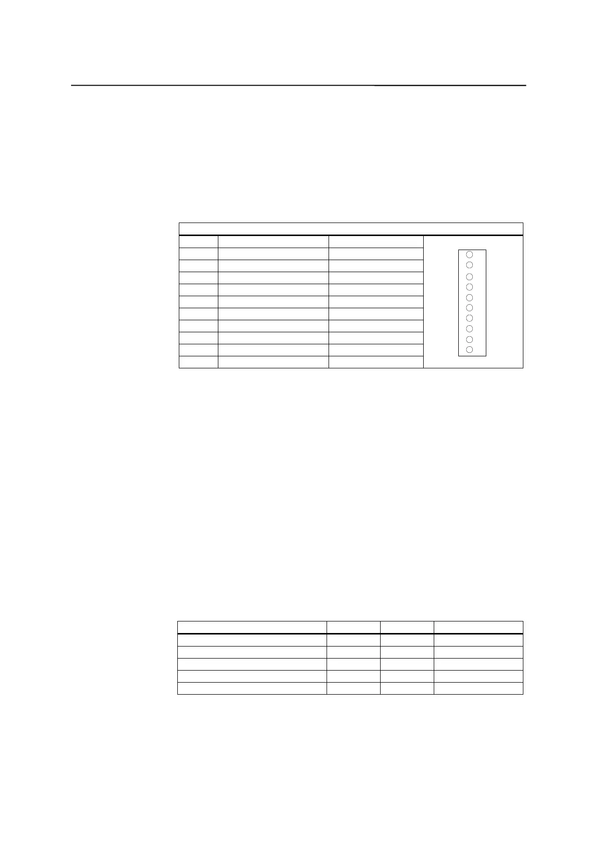
Pin assignment of connector on the CNC side
BERO input interface
Connector designation: X20
DI
Connector type: 10-pin plug connector
Table 2–11 Pin assignment of connector X20
X20
Pin Signal Type
1 NCRDY_1 K
2 NCRDY_2 K
3 I0 / BERO1 DI
4 I1 / BERO2 DI
5 I2 / BERO3 DI
6 I3 / BERO4 DI
7 I4 / MEPU1 Not defined
8 I5 / MEPU2 Not defined
9L- VI
10 L- VI
11
20
Signal description:
NCRDY_1…2 NC-READY-Contact, max. current is 2A at 150VDC or
125VAC)
I0 ... I5 Fast digital input 0 … 5
BERO1 ... BERO4 BERO-Input for axis 1 ... 4
L- Reference potential for digital input
Signal type
K Switching contact
4 BERO inputs
These inputs are 24V P-switching. Switches or non-contact sensors, e.g.
inductive proximity switches(BERO) can be connected.
They can be used as switches for reference points, for example:
BERO1 – X axis
BERO2 – Z axis
Table 2-12 Electrical parameters of the digital inputs
Parameter Value Unit Note
“1” signal, voltage range 11…30 V
“1” signal, current consumption 6…15 mA
“0” signal, voltage range -3…5 V Or input open
Signal delay 0
Æ
115us
Signal delay 1
Æ
0 150 us
NC–READY output
Readiness in the form of a relay contact (NO); must be integrated into the
EMERGENCY STOP circuit.

 Loading...


