Installing the Control System
2.3 Connecting the individual components
2-31
SINUMERIK 802S
6FC5 597–2AA00–0BP2 (01.02)
VO Voltage output
I Input (5 V signal)
Handwheels
Two electronic handwheels can be connected which must meet the following requirements:
Transmission method: 5 V square–wave (TTL level or RS422)
Signals: Track A as true and negated signal (U
a1
, U
a1
)
Track B as true and negated signal (U
a2
, U
a2
)
Max. output frequency: 500 kHz
Phase offset between
tracks A and B: 90° "30°
Supply: 5 V, max. 250 mA
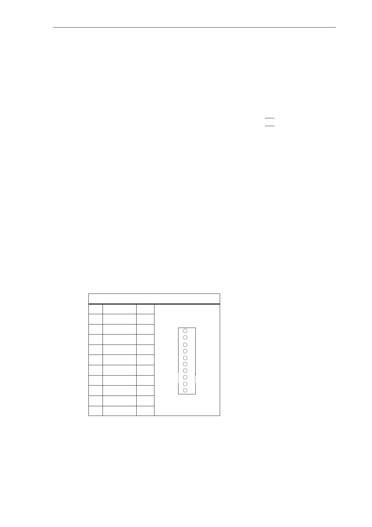
2.3.7 Connecting NCREADY (X20)
Pin assignment of the connector on the ENC side
BERO input interface
Connector designation: X20
DI
Connector type: 10–pin plug connector
Table 2-14Pin assignment of connector X20
X20
Pin Name Type
11 NCRDY_1 K
12 NCRDY_2 K
11
13 reserved DI
14 reserved DI
15 reserved DI
16 reserved DI
17 reserved DI
18 reserved DI
20
19 reserved VI
20
20 reserved VI
Signal names
NCRDY_1...2 NC Ready (NCREADY contacts 1...2)
BERO1...BERO4 BERO input for axes 1 ... 4

 Loading...


