Installing the Control System
2.5 Grounding
2-38
SINUMERIK 802S
6FC5 597–2AA00–0BP2 (01.02)
2.5 Grounding
Ground connections
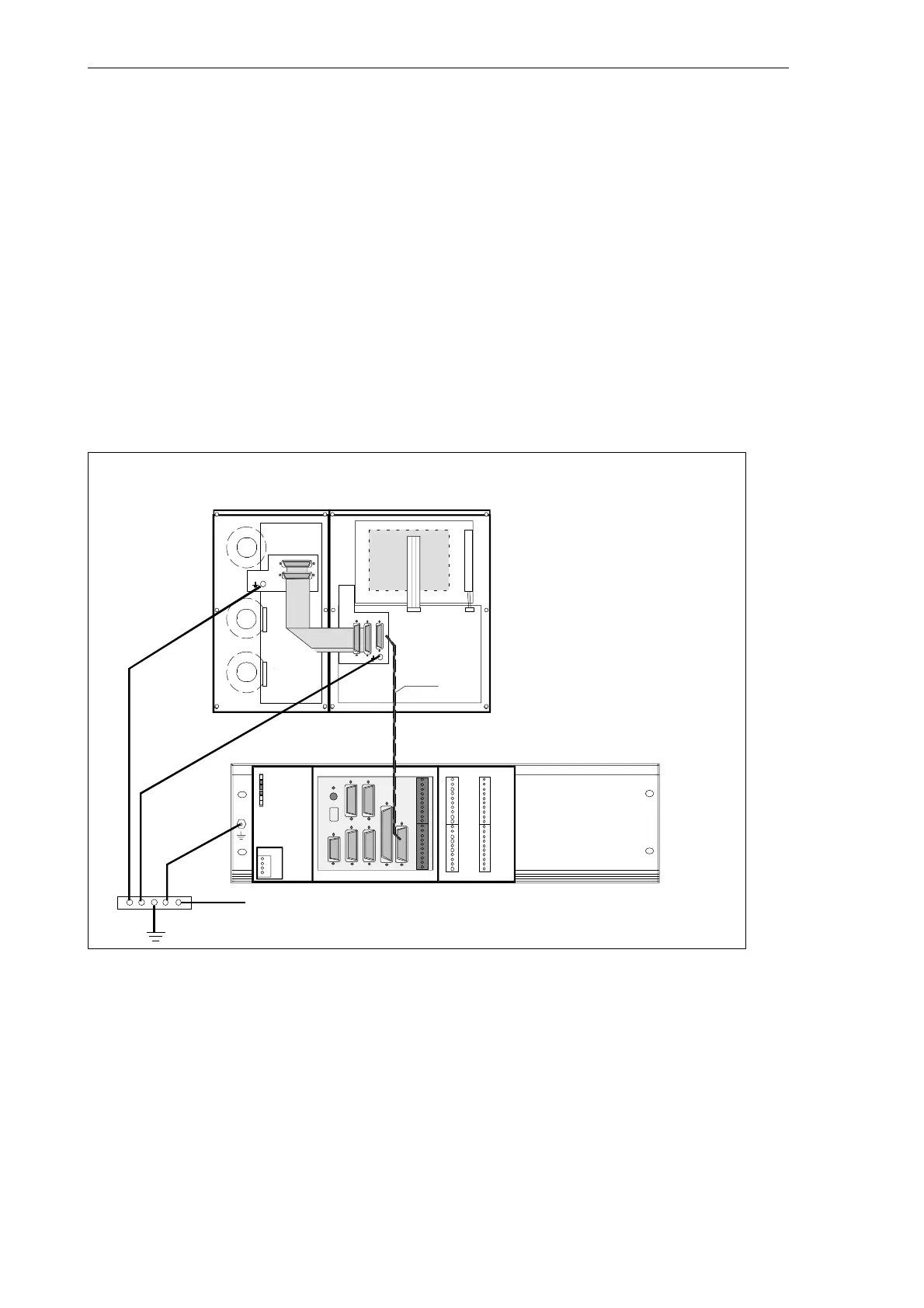
The following ground connections must be implemented:
S Busbar for ENC, DI/O
S OP020 operator panel
S Machine control panel (MCP)
The ground connections for the MCP/OP020 must take into account installation in the ma-
chine or a panel.
In the case of cubicle installation, the grounding points must be connected to the grounding
bar (see Fig. 2-7).
DC24V X1
ERR
DIAG
POK
L+
M
L+
M
X2003 X2005
X2004 X2006
0
1
2
3
4
5
6
7
M
L+
0
1
2
3
4
5
6
7
M
8
9
10
11
12
13
14
15
M
L+
8
9
10
11
12
13
14
15
M
IN
OUT
RS232
X2
SPINDLE
X5
ENCODER3
X6
OPI
X8
AXIS
X7
X10
MPG
DI
X20
ENCODER2
X4
ENCODER1
X3
ECU
DI/O16
Grounding bar
to chassis
Installation in a cu-
bicle or machine
Shielded signal
cable
OP020
MCP
LCD signal-
connector
CFL
Fig. 2-7 Grounding diagram for MCP/OP020 installation in a cubicle or machine

 Loading...


