Start-Up
4.3 Starting up the PLC
4-67
SINUMERIK 802S
6FC5 597–2AA00–0BP2 (01.02)
The Documentation “S7–200 Automation System, System Manual“ describes how this tool is
operated for S7–200. The PLC 802 Programming Tool is to be understood as a subset of this
Documentation.
Compared with the S7–200 MicroWin basic system, please note the following:
S The PLC 802 Programming Tool is delievered in the English language version.
S The user program can only be programmed using ladder diagram.
S Only a subset of the S7–200 programming language is supported.
S The compilation of the user program is carried out either offline on a programming device
(PG)PC or semi–automatically when downloading into the control system.
S The project can be loaded into the control system (download).
S It is also possible to load the project from the control system (upload).
S Direct data addressing is not possible; therefore, no programming errors will rsult during
the operation.
S The data/process information must be managed by the user in accordance with the parti-
cular type.
Example:
Information 1 T value DWord memory size (32–bit)
Information 2 Override Byte memory size (8–bit)
User data
Byte 0 DWord (Information 1)
Byte 4 Byte (Information 2)
The user is not allowed to access both of these data at the same time; otherwise, the rele-
vant data access rules must be observed.
S Furthermore, the data direction in the memory model (alignment) and the data type must
be observed for all data.
Example:
Flag bit MB0.1,MB3.5
Flag byte MB0,MB1,MB2
Flag word MW0,MW2,MW4
MW3, MW5 ... are not permissible
Flag double–word MD0,MD4,MD8
MD1,MD2,MD3, MD5 ... are not permissible
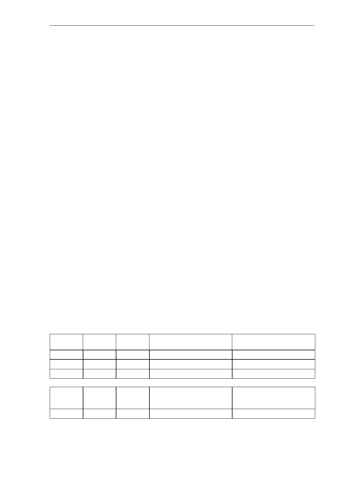
Table 4-6 PLC data types permitted in the control system
Data Type
Size Address
Alignment
Range for Logic Operations Range for Arithmetical Opera-
tions
BOOL 1 bit 1 0, 1 –
BYTE 1 byte 1 00 ... FF 0 ... +255
WORD 2 bytes 2 0000 ... FFFF –32 768 ... + 32 767
DWORD
(Double
Word)
4 bytes 4 0000 0000 ... FFFF FFFF –2 147 483 648 ...
+2 147 483 647
REAL 4 bytes 4 – $10
–37
... $10
38