5.8 Axis / spindle-specific signals
6LJQDOVWRD[LV'%[
[ !$[LV
[ !$[LV
6LJQDOVIURPD[LV'%[
[ !$[LV
[ !$[LV
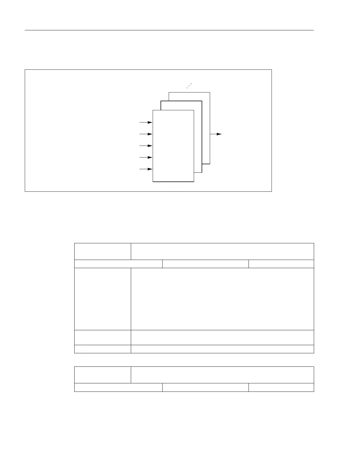
&ODPSLQJLQSURJUHVV'%['%;
+DUGZDUHOLPLWVZLWFKSOXV'%['%;
+DUGZDUHOLPLWVZLWFKPLQXV'%['%;
QGVRIWZDUHOLPLWVZLWFKSOXV'%['%;
QGVRIWZDUHOLPLWVZLWFKPLQXV'%['%;
$[LV
$[LV
$[LV
$[LVPRQLWRULQJ
IXQFWLRQV
(QFRGHUIUHTXHQF\
RYHUOLPLWHG
'%['%;
Figure 5-1 PLC interface signals for axis monitoring
5.8.1 Transferred axis-specific M, S functions
DB370x
DBD0
M function for spindle
Signal(s) from axis/spindle (NCK → PLC), axis-specific
Edge evaluation: Signal(s) updated: Cyclic
Application Generally, the M functions are output for specific channels in DB2500. In the
range DB2500 DBB1000 ... these are only present for one PLC cycle; in
DB2500 DBD3000 ... up to a new output.
Selected "M functions for the spindle" are available as integer number actual
value of the PLC in this IS "M function for spindle".
●
M3→ Value: 3
● M4→ Value: 4
●
M5→ Value: 5
corresponding to ... IS "S function for spindle" (DB370x DBD4), axis-specific
IS auxiliary function transfer from NC channel (DB2500)
Note for the reader Function Manual Basic Functions S1
DB370x
DBD4
S function for spindle
Signal(s) from axis/spindle (NCK → PLC), axis-specific
Edge evaluation: Signal(s) updated: Cyclic
Detailed descriptions of interface signals
5.8 Axis / spindle-specific signals
Parameter Manual
404 Parameter Manual, 08/2015, 6FC5397-8EP40-0BA1

 Loading...


