To the MCP
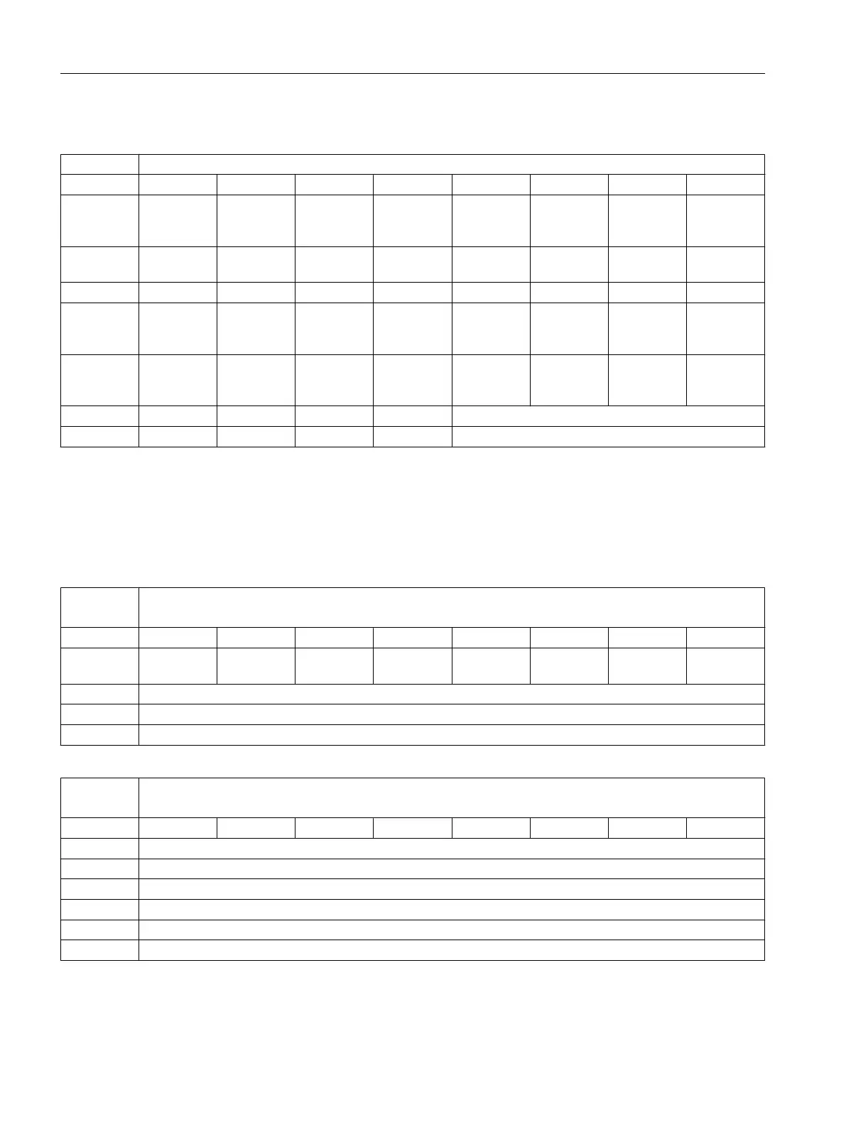
DB1100 To MCP [r/w]
Byte Bit 7 Bit 6 Bit 5 Bit 4 Bit 3 Bit 2 Bit 1 Bit 0
DBB0 M01 PRO‐
GRAM
TEST
MDA SINGLE
BLOCK
AUTO REF.
POINT
JOG HAND
WHEEL
DBB1 Key 7 TAIL
STOCK
INT. EXT. CHUCK TOOL
CHANGE
COOLANT LAMP ROV
DBB2 100 (INC) 10 (INC) 1 (INC) Key 12 Key 11 Key 10 Key 9 Key 8
DBB3 Axis tra‐
versing key
(↑x)
Key 13 CYCLE
START
CYCLE
STOP
RESET SPINDLE
RIGHT
SPINDLE
STOP
SPINDLE
LEFT
DBB4 Key 21 Axis tra‐
versing key
(↓x)
Key 19 Axis tra‐
versing key
(→z)
RAPID Axis tra‐
versing key
(←z)
Key 15
DBB8 1
1)
1
1)
7 SEG LED1
2)
DBB9 1
1)
1
1)
7 SEG LED2
2)
1)
To ensure the correct display of the active tool number, make sure that you set Bit 4 and Bit 5 to 1.
2)
You can set only values 0 to 9 for each 7-segment LED (LED1 and LED2).
6.2.2 Reading/writing NC data: Job
DB1200
Reading / writing NC data [r/w]
PLC -> NCK interface
Byte Bit 7
Bit 6 Bit 5 Bit 4 Bit 3 Bit 2 Bit 1 Bit 0
0 Write varia‐
ble
Start
1 Number of variables
2
3
DB1200 ...
1203
Reading / writing NC data [r/w]
PLC -> NCK interface
Byte Bit 7 Bit 6 Bit 5 Bit 4 Bit 3 Bit 2 Bit 1 Bit 0
1000 Variable index
1001 Area number
1002 Column index for the NCK variable x (WORD)
1003 Line index for the NCK variable x (WORD)
1006
1008 Writing: data to NCK variable x (data type of the variables: 1 to 4 bytes)
PLC user interface
6.2 MCP
Parameter Manual
454 Parameter Manual, 08/2015, 6FC5397-8EP40-0BA1

 Loading...


