Signal state 0 or edge
change 1 → 0
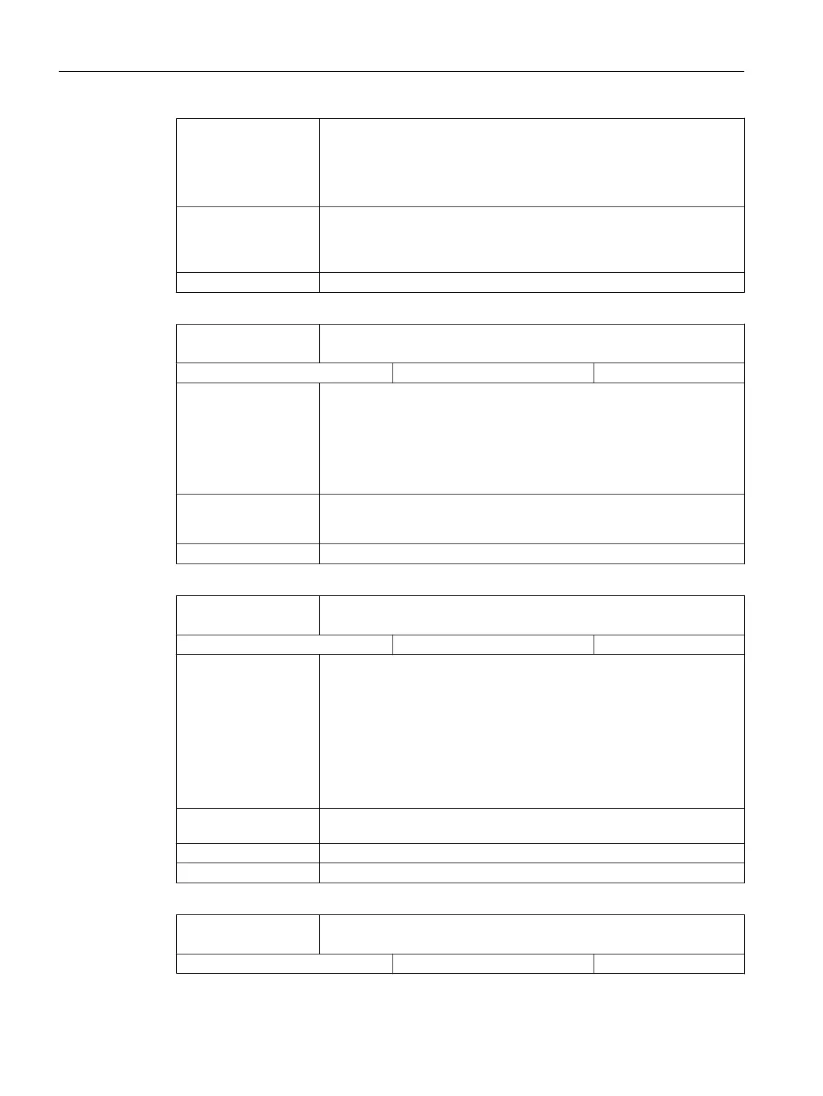
The machine axis is operated as an axis.
The IS's to the axis (DB380x DBX1000 to DB380x DBX1003) and from the
axis (DB390x DBX1000 to DB390x DBX1003) are valid.
The IS's to the spindle (DB380x DBX2000 to DB380x DBX2003) and from
the spindle (DB380x DBX2000 to DB380x DBX2003) are invalid.
Application If a spindle is sometimes also used as a rotary axis on a machine tool (lathe
with spindle / Caxis or milling machine with spindle / rotary axis for rigid
tapping), then the
IS "Spindle / no axis" can be used to identify as to whether
the machine axis is in the axis or spindle mode.
Note for the reader Function Manual Basic Functions S1
DB390x
DBX0.2
Encoder limit frequency exceeded 1
Signal(s) from axis / spindle (NCK → PLC)
Edge evaluation: No Signal(s) updated: Cyclic
Signal state 1 The limit frequency set in MD36300 ENC_FREQ_LIMIT (encoder limit fre‐
quency)
has been
exceeded. The reference point for the position measuring
system involved has been lost (IS: Referenced/synchronized is in signal
state 0). Closed-loop position control is no longer possible. Spindles continue
to operate with closed-loop speed control.
Axes are stopped with a fast stop (with open-circuit position control loop)
along a speed setpoint ramp.
Signal state 0 The limit frequency set in MD36300 is no longer exceeded.
For the edge change 1 → 0, the encoder frequency must have fallen below
the value of MD36302 ENC_FREQ_LIMIT_LOW (% value of MD 36300).
Note for the reader Function Manual Basic Functions A3
DB390x
DBX0.4
Referenced / synchronized 1
Signal(s) from axis / spindle (NCK → PLC)
Edge evaluation: Signal(s) updated:
Signal state 1 or edge
change 0 → 1
Axes:
When being referenced,
if the machine axis has reached the reference point
(incremental measuring systems) or the target point (for length measuring
system with distance-coded reference marks), then the machine axis is ref‐
erenced and the IS "Referenced / synchronized 1" (for position measuring
system 1) is set.
Spindles:
After "power-on", a spindle is synchronized the latest after one spindle rev‐
olution (zero mark) or when passing the BERO.
Signal state 0 or edge
change 1 → 0
The machine axis / spindle with position measuring system 1 is not refer‐
enced/synchronized.
corresponding to ... DB380x DBX0.5 (position measuring system 1)
Note for the reader Function Manual Basic Functions R1, S1
DB390x
DBX0.5
Referenced / synchronized 2
Signal(s) from axis / spindle (NCK → PLC)
Edge evaluation: Signal(s) updated:
Detailed descriptions of interface signals
5.8 Axis / spindle-specific signals
Parameter Manual
428 Parameter Manual, 08/2015, 6FC5397-8EP40-0BA1

 Loading...


