EasyManuals Logo
Home>Smartrise>Controller>C4

Smartrise C4 Manual

Default Icon
32 pages
To Next Page IconTo Next Page
To Previous Page IconTo Previous Page
Page #11 background imageLoading...
Page #11 background image
Load Weighing Device
September 29,2021 ©2021 Smartrise Engineering, Inc. All Rights Reserved Page 3
The table below lists wiring configuration of Power to the Base board of the LWD.
Table 2: Wiring Configuration of Power to the Base Board of the LWD
Power
LWD Base Board Connector
24V
Pin 1
REF
Pin 2
To connect the CAN network, connect the CANH and CANL as follows:
If the LWD is in the machine room, connect the network to AN+ and AN-.
If the LWD is located on the Cartop, connect the network to C3H and C3L.
Each sensor had to be tested individually to verify the sensors has been correctly installed. See
Adjustments steps 1-12.
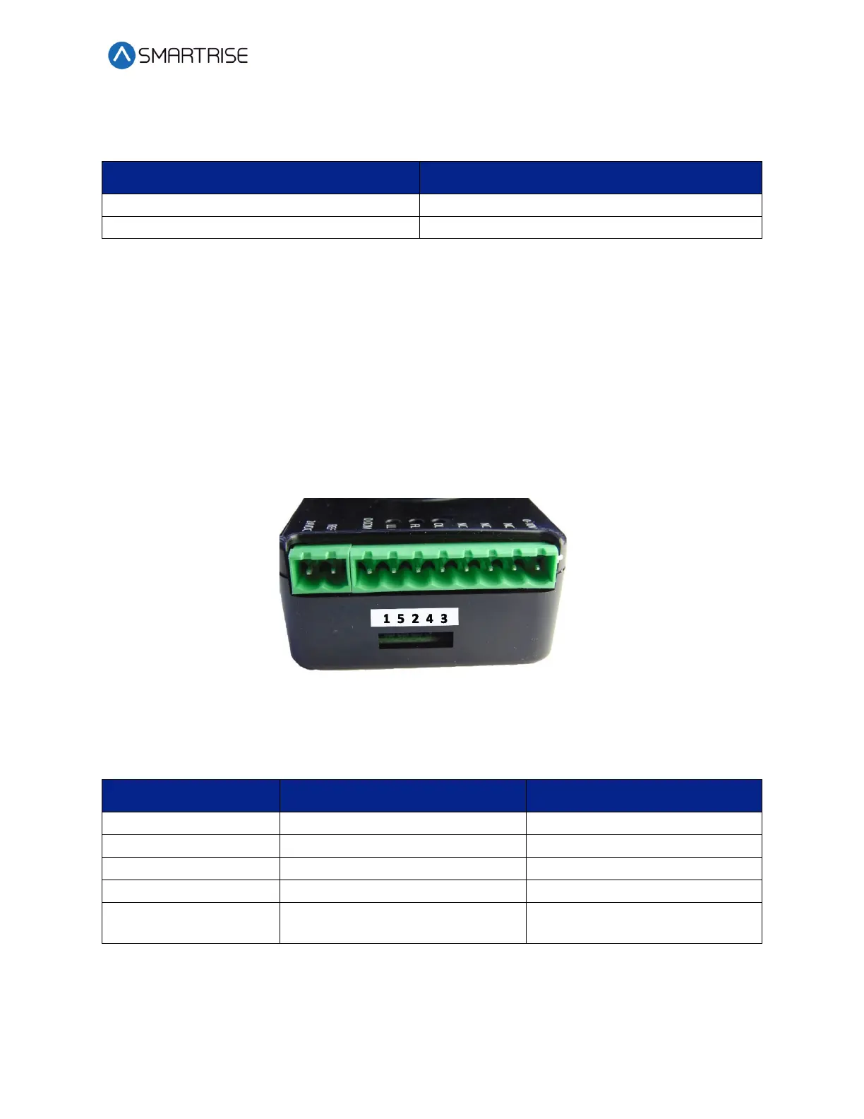
LEDs
The LEDs display the status of the LWD.
Figure 4: LED Location
The table below lists LED Indicators.
Table 3: LED Indicators
LED
Indicator
Normal Status
O1 (Green)
Power LED
On
O2 (Green)
Heartbeat
Blinks 1Hz
O3 (Red)
Fault
Off (On indicates a fault)
O4 (Orange)
N/A
Off
O5 (Green)
Serial Comm.
Blinks to reflect data traffic from
the C4 controller

Table of Contents

Other manuals for Smartrise C4

Questions and Answers:

Smartrise C4 Specifications

General IconGeneral
BrandSmartrise
ModelC4
CategoryController
LanguageEnglish

Related product manuals