3-46
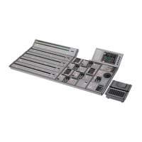
MVS-8000 System
SYSTEM SETUP
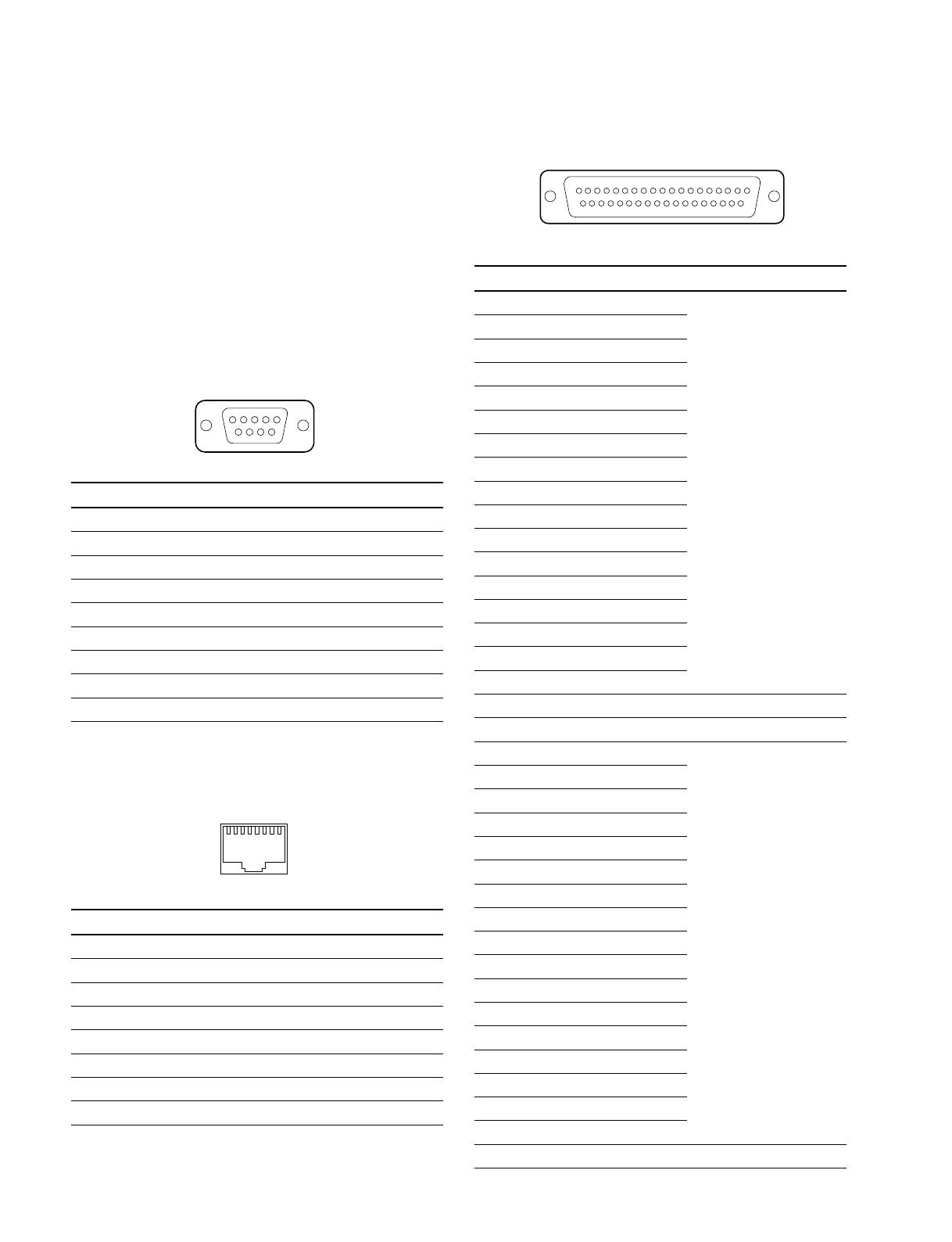
3-8. Pin Output
_ EXT VIEW _
1
5
69
1
8
_ EXT VIEW _
3-8-4. DCU-8000
The input/output signals of the connectors at the rear panel
are as follows.
n
<CONTROLLER> indicates a controlling device.
<DEVICE> indicates a controlled device.
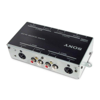
MKS-8700
SERIAL TALLY 1, 2 : RS-422A (D-sub 9-pin, Female)
<CONTROLLER> to Tally Interface Unit (*1)
Pin No. Signal name Function
1 FG Frame ground
2RX_ Received data (_)
3TX+ Transmitted data (+)
4 GND Common ground
5 _ No Connection
6 GND Common ground
7RX+ Received data (+)
8TX_ Transmitted data (_)
9 _ No Connection
(*1) :
TALLY INTERFACE UNIT BKDS-6080 and others.
PERIPH :
100BASE-TX, RJ-45 (8-pin)
Pin No. Signal name Function
1TX+ Transmitted data (+)
2TX_ Transmitted data (_)
3RX+ Received data (+)
4 _ No Connection
5 _ No Connection
6RX_ Received data (_)
7 _ No Connection
8 _ No Connection
119
2037
TALLY/GPI IN 1-34 : D-sub 37-pin, Female
INPUT x 34, TTL, 2 INPUT TTL/+12 V Switchable (*2)
_EXT VIEW_
Pin No. Signal name Function
1 TALLY/GPI IN 1 Tally/GPI inputs
2 TALLY/GPI IN 3
3 TALLY/GPI IN 5
4 TALLY/GPI IN 7
5 TALLY/GPI IN 9
6 TALLY/GPI IN 11
7 TALLY/GPI IN 13
8 TALLY/GPI IN 15
9 TALLY/GPI IN 17
10 TALLY/GPI IN 19
11 TALLY/GPI IN 21
12 TALLY/GPI IN 23
13 TALLY/GPI IN 25
14 TALLY/GPI IN 27
15 TALLY/GPI IN 29
16 TALLY/GPI IN 31
17 TALLY/GPI IN 33 (*2)
18 GND Ground
19 GND Ground
20 TALLY/GPI IN 2 Tally/GPI inputs
21 TALLY/GPI IN 4
22 TALLY/GPI IN 6
23 TALLY/GPI IN 8
24 TALLY/GPI IN 10
25 TALLY/GPI IN 12
26 TALLY/GPI IN 14
27 TALLY/GPI IN 16
28 TALLY/GPI IN 18
29 TALLY/GPI IN 20
30 TALLY/GPI IN 22
31 TALLY/GPI IN 24
32 TALLY/GPI IN 26
33 TALLY/GPI IN 28
34 TALLY/GPI IN 30
35 TALLY/GPI IN 32
36 TALLY/GPI IN 34 (*2)
37 GND Ground
 Loading...