2-16
MVS-8000 System
SYSTEM SETUP
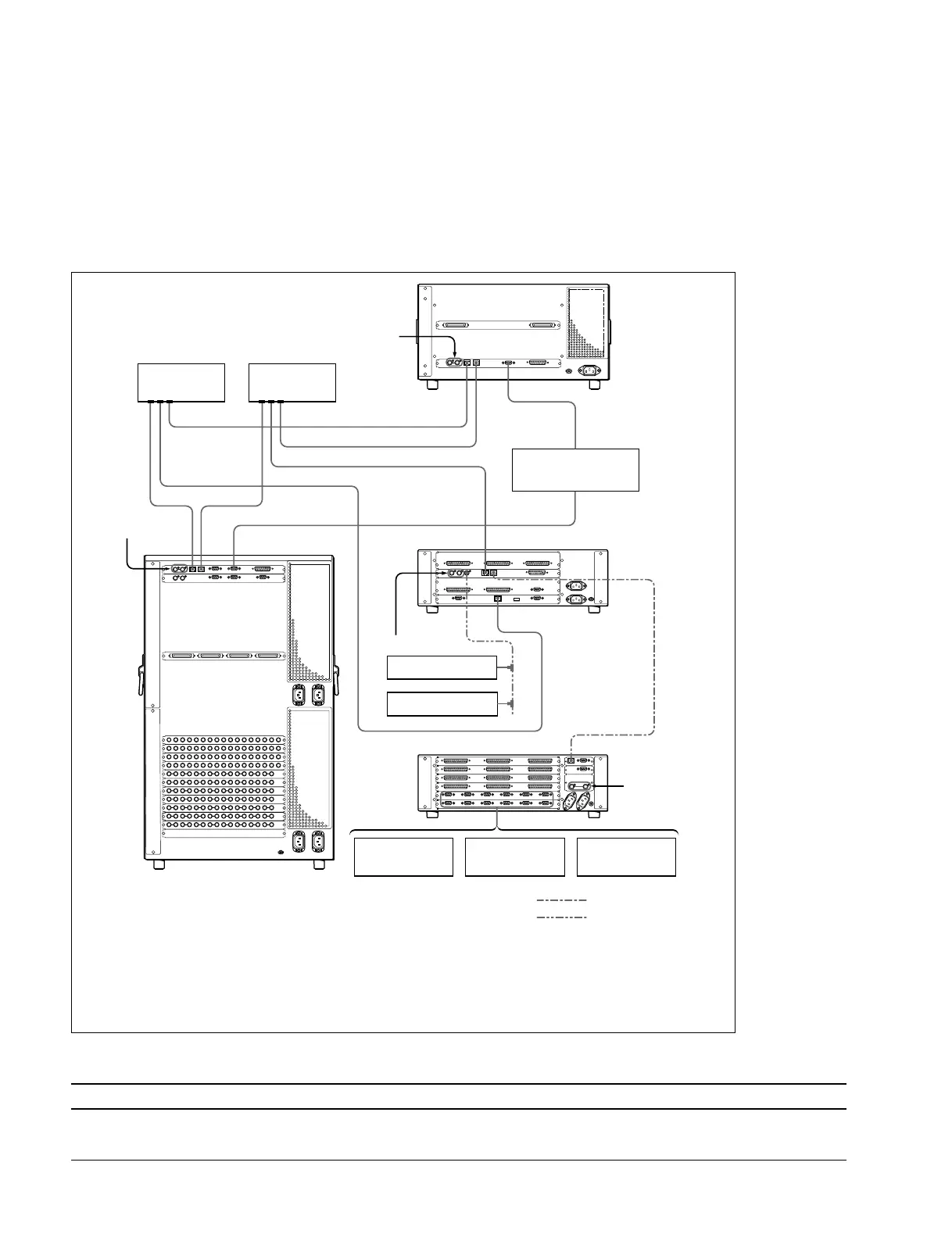
2-7. MVS-8000 System Control Cabling
2-7-1. Cabling
The MVS system uses Ethernet, serial, parallel, USB and S-BUS control. Tally and GPI control are also
available from DCU-8000 and CCP-8000 (System Control Unit).
MVS-8000 system control cabling
2-7. MVS-8000 System Control Cabling
Reference video
signal (*2)
CTRL
CTRL
EDITOR
DATA LAN
REMOTE
DATA CTRL REMOTE 1
DATA
PERIPH
PERIPH
Ethernet switch
(*1)
Ethernet switch
(*1)
Reference video signal (*2)
Reference video
signal (*2)
Reference video
signal (*2)
DME Processor Pack
MVE-8000
Editing Control System
BVE-9100
System Control Unit
MKS-8010
BKS-R series
HDS-X series
Device Control Unit Pack DCU-8000
VTR DDR
Audio mixer
Switcher Processor Pack
MVS-8400/8300/8200
Crossover cable
BNC cable
(*1) : Connect each LAN (CTRL, DATA) to the separate Ethernet switches respectively.
However, a single Ethernet switch can be used for connecting each LAN.
For information about Ethernet switches that can be used in an MVS system, refer to “2-7-2. LAN
Requirements” and “3-4. Ethernet Switch Settings”.
For detailed information about setting up the Ethernet switch, refer to the documentation -supplied with the switch.
(*2) : Terminate the system with the 75 Z terminator supplied. The 75 Z terminator is supplied with the equipment.
Supplied and required cables
Cable Description Quantity Part No.
LAN cable RJ-45 *_
Conforms to the IEEE802.3
Ethernet 100 BASE-TX
* : Quantity depends on the configuration.
 Loading...