2-15
MVS-8000 System
SYSTEM SETUP
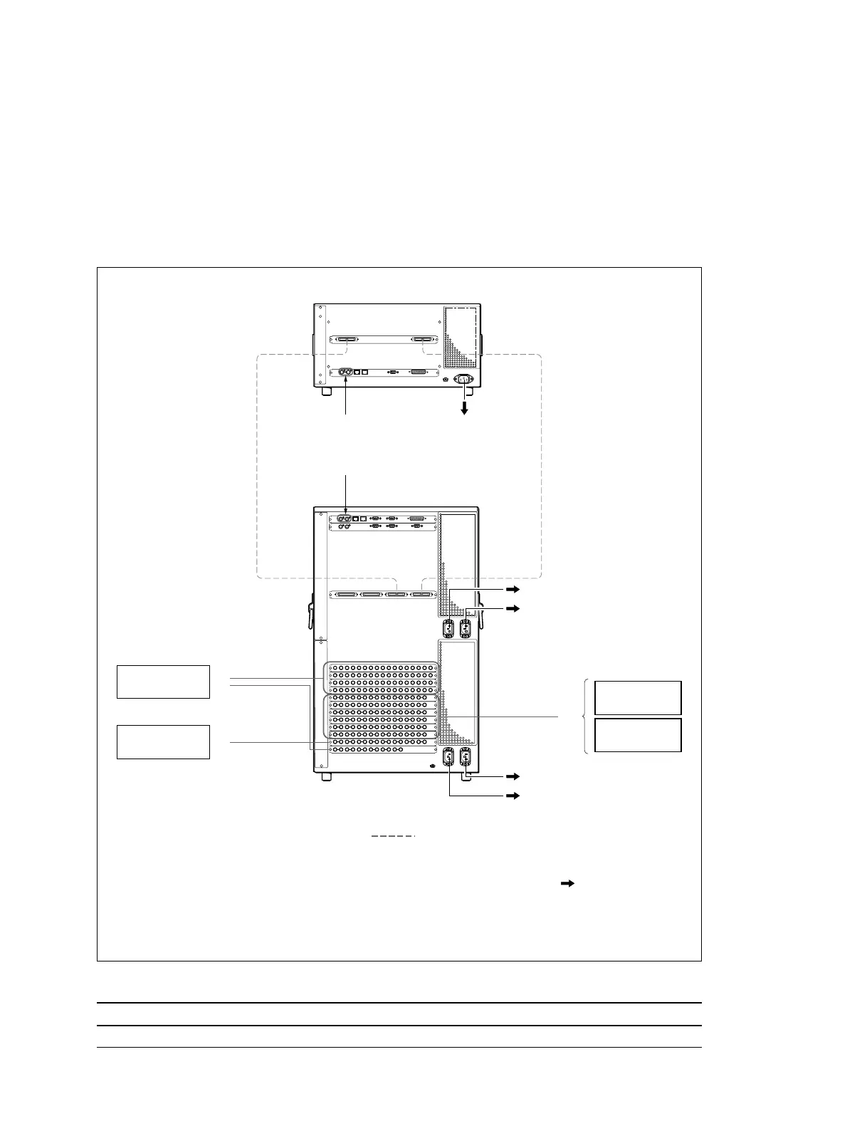
2-6. MVS-8000 System Video Cabling
The MVS-8000 system connections is shown in the illustration.
Different video and control wiring configurations may be created to meet individual facility requirements.
Each input can be assigned to any CCP panel source select button, and any MVS system video signal can
be assigned to any pair of output connectors.
MVS-8000 system video cabling
Supplied and required cables
Cable Description Quantity Part No.
DME V/K Interface MDR 68-pin Female 2 Supplied with MVE-8000
2-6. MVS-8000 system video Cabling
PRIMARY INPUTS
1 to 68
MONITOR OUTPUTS
1 to 8
Reference video
signal (*3)
Reference video signal (*3)
PRIMARY INPUTS
69 to 80
VTR
Camera
VTR
Routing Switcher
MONITOR
Switcher Processor Pack
MVS-8400/8300/8200
75-pin Cable
SWITCHER ASWITCHER B
DME 1B
DME 1A
AC100 to 240 V Power Supply (*2)
AC100 to 240 V Power Supply (*1)
AC100 to 240 V Power Supply (*2)
AC100 to 240 V Power Supply (*2)
AC100 to 240 V Power Supply (*2)
8
8
8
MONITOR
8
OUTPUTS 1 to 48
Video Signal Input
Video Signal Output
AC Power Supply
5
5
5
Video/Key Signal
DME Processor Pack
MVE-8000
(*1) : For the AC power cord, refer to “Optional Items” of the “DME Processor Pack MVE-8000” Operation Manual.
(*2) : For the AC power cord, refer to “Optional Items” of the “Multi-Format Switcher Processor MVS-8000”
Operation Manual.
(*3) : Terminate the system with the 75 Z terminator supplied with this unit.
 Loading...