1-25
MVS-8000 System
SYSTEM SETUP
1-5. Functional Overview
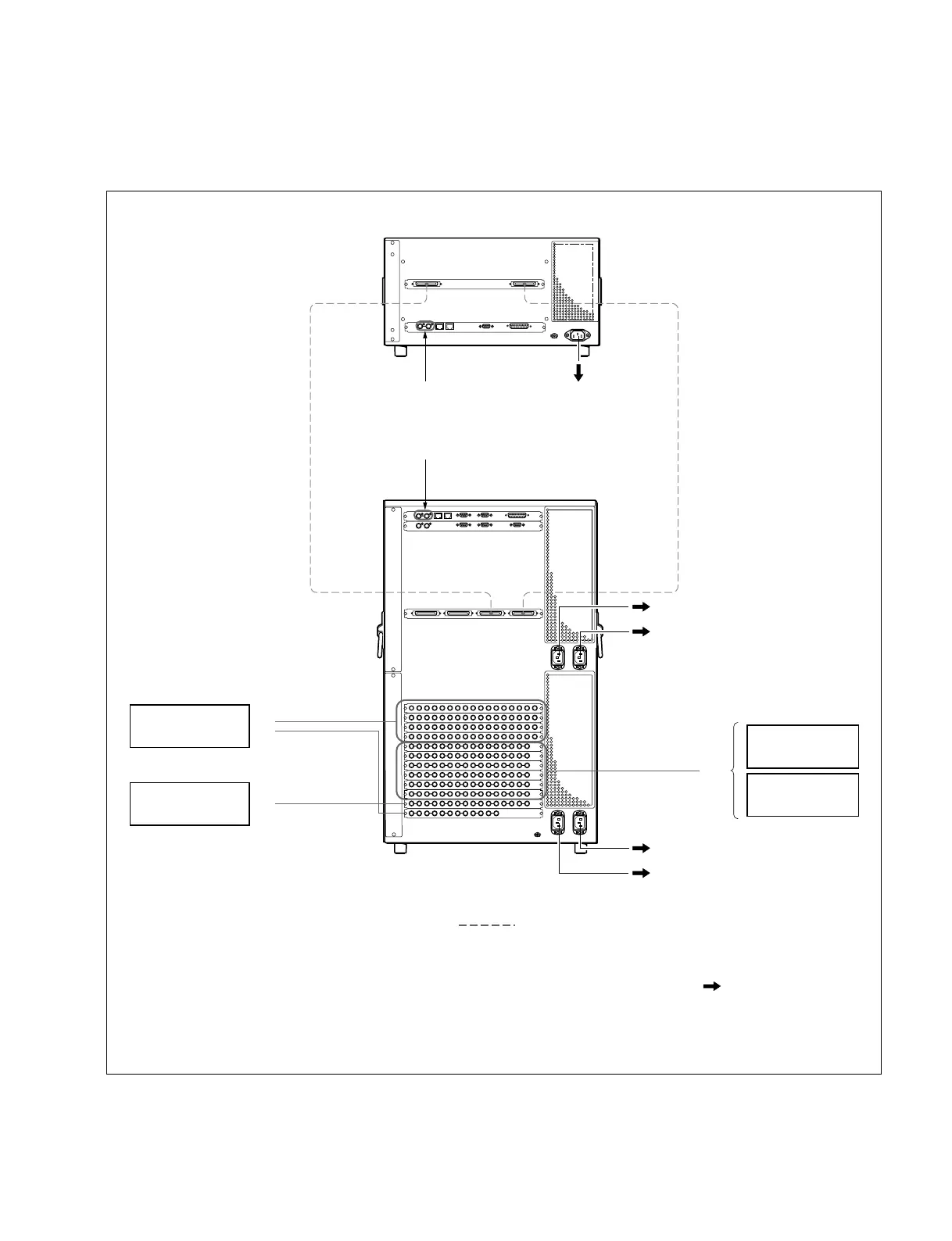
1-5-1. Video Signal Flow
(*1) : For the AC power cord, refer to “Optional Items” of the “DME Processor Pack MVE-8000” Operation Manual.
(*2) : For the AC power cord, refer to “Optional Items” of the “Multi-Format Switcher Processor MVS-8000” Operation Manual.
(*3) : Terminate the system with the 75 Z terminator supplied with this unit.
PRIMARY INPUTS
1 to 68
MONITOR OUTPUTS
1 to 8
Reference video
signal (*3)
Reference video signal (*3)
PRIMARY INPUTS
69 to 80
VTR
Camera
VTR
Routing Switcher
MONITOR
Switcher Processor Pack
MVS-8400/8300/8200
75-pin Cable
SWITCHER ASWITCHER B
DME 1B
DME 1A
AC100 to 240 V Power Supply (*2)
AC100 to 240 V Power Supply (*1)
AC100 to 240 V Power Supply (*2)
AC100 to 240 V Power Supply (*2)
AC100 to 240 V Power Supply (*2)
8
8
8
MONITOR
8
OUTPUTS 1 to 48
Video Signal Input
Video Signal Output
AC Power Supply
5
5
5
Video/Key Signal
DME Processor Pack
MVE-8000
1-5. Functional Overview
 Loading...