85
Basic Switcher Settings
Chapter 3 Preparations
a) Connector is disabled
6
If you selected Y/CB/CR in step 5, rotate the F4 knob to select the level of
the component input signals.
Betacam: Betacam level
SMPTE: SMPTE level
Settings of step 6 can be available only when the switcher’s video format
(see page 71) is set to 525/59, 720/59, or 1080/59.
Specifying the signal type of DVI input signals
When you are using the optional BKDF-912 2 DVI Input Board, specify the
picture size and aspect ratio conversion modes for the DVI signals that will be
input to the board.
For more information about the BKDF-912, see page 31. For information about
how to install it, see page 39.
Depending on the video format setting of this switcher (page 71), select the DVI
input signal resolution from the values in the following table. If you specify a
resolution other than the values shown in the table, images may be unable to be
reproduced normally.
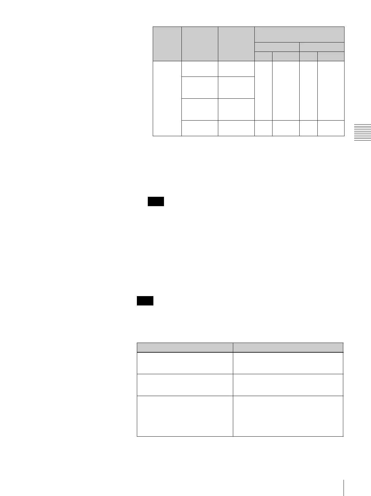
Y/CB/CR COMP/Y Luminance
(Y) signal
IN09 IN13 IN17 IN21
B-Y Color
difference
(B-Y) signal
R-Y Color
difference
(R-Y) signal
COMP Composite
signal
IN10 IN14 IN18 IN22
Note
Setting
of step 5
Name of
BKDF-911
connector
Input signal BKDF-911 installation position
and channel number
Lower tray Upper tray
Left Center Left Center
Note
Video format setting DVI input signal resolution
525/59 or 625/50 VGA (640 × 480)
SVGA (800 × 600)
XGA (1024 × 768)
720/50 or 720/59 XGA (1024 × 768)
SXGA (1280 × 1024)
WXGA (1280 × 768)
1080/50 or 1080/59 XGA (1024 × 768)
SXGA (1280 × 1024)
WXGA (1280 × 768)
UXGA (1600 × 1200)
WSXGA (1680 × 1050)
WUXGA (1920 × 1200)

 Loading...