74
Basic Switcher Settings
Chapter 3 Preparations
4
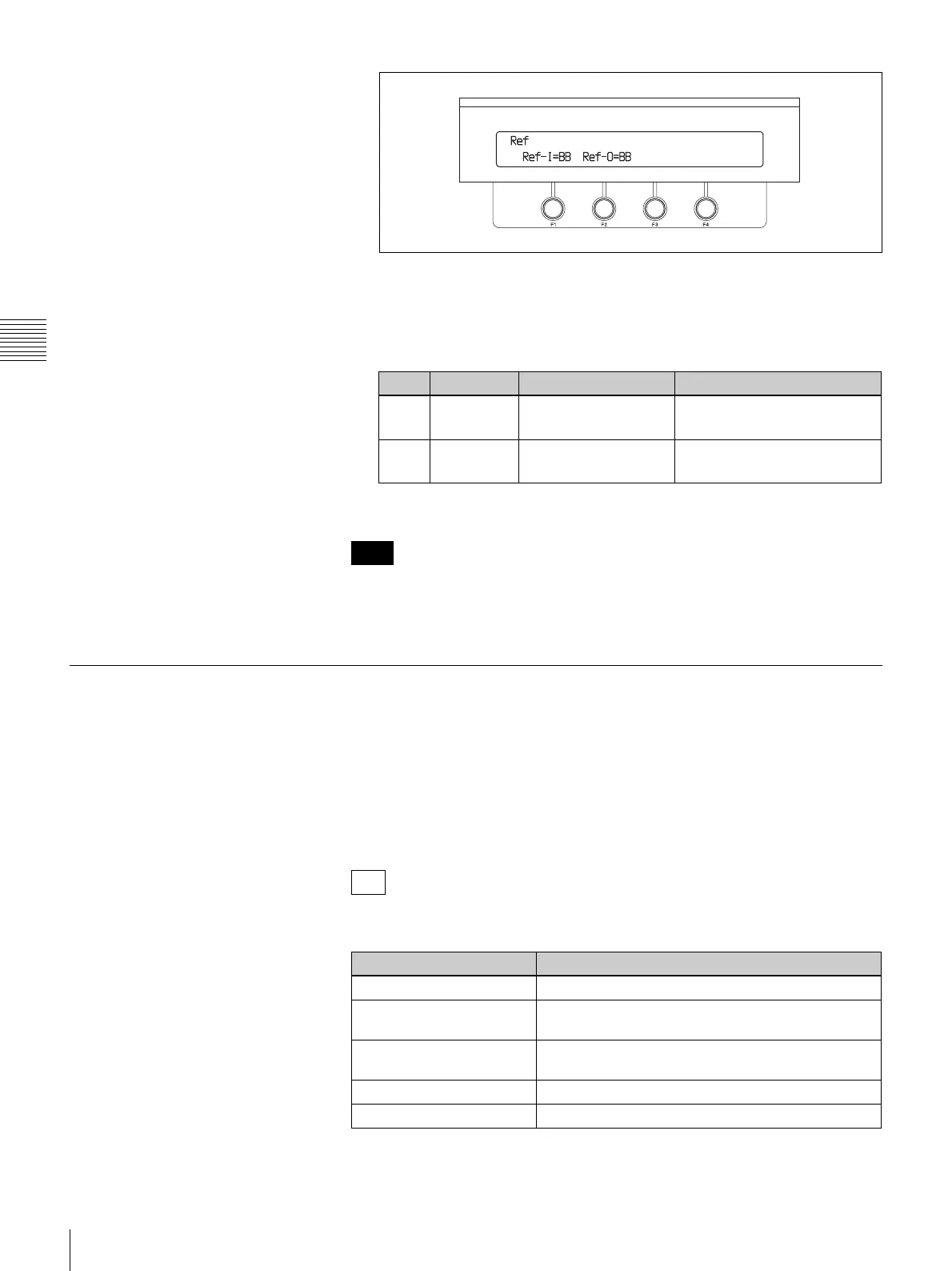
Make the reference sync signal settings.
Rotate the F1 knob to specify an input sync signal, and rotate the F2 knob
to specify an output sync signal.
The correspondence between knobs and parameters is as follows.
a) Selectable only when the video format is set to an HD signal (720/50, 720/59, 1080/50, 1080/59)
(see page 71).
When the video format is set to 1080/59 or 525/59, and you set Ref-O to BB,
the setting of Set (see page 71) in the System >Type sub menu is also reflected
in the reference sync signal.
Making Settings Related to Input Signals
Changing signal display names
You can change the input signal names displayed in menus to user-specified
names up to four alphanumeric characters long.
To change the names, save a text file containing a list of the current signal names
to a USB flash drive, edit the names on a computer, and then load the edited list
into the switcher.
Signals have the following display names when the switcher is shipped from the
factory.
Knob Parameter Description Setting range
F1 Ref-I Input reference sync
signal
BB: Black burst signal
TriS: Tri-level sync signal
a)
F2 Ref-O Output reference sync
signal
BB: Black burst signal
TriS: Tri-level sync signal
a)
Note
Tip
Signal name Signal
BLK Black signal
IN01 to IN08 (numbers are
channel numbers)
Input signals connected to the SDI IN 1 to 8
connectors
IN09 to IN24 (numbers are
channel numbers)
Input signals connected to optional input expansion
boards, when the optional boards are installed
STL1 to STL4 Still images stored in the processor unit
MAT1 to MAT4 Color matte signals for use in backgrounds, etc.
 Loading...