90
Basic Switcher Settings
Chapter 3 Preparations
2
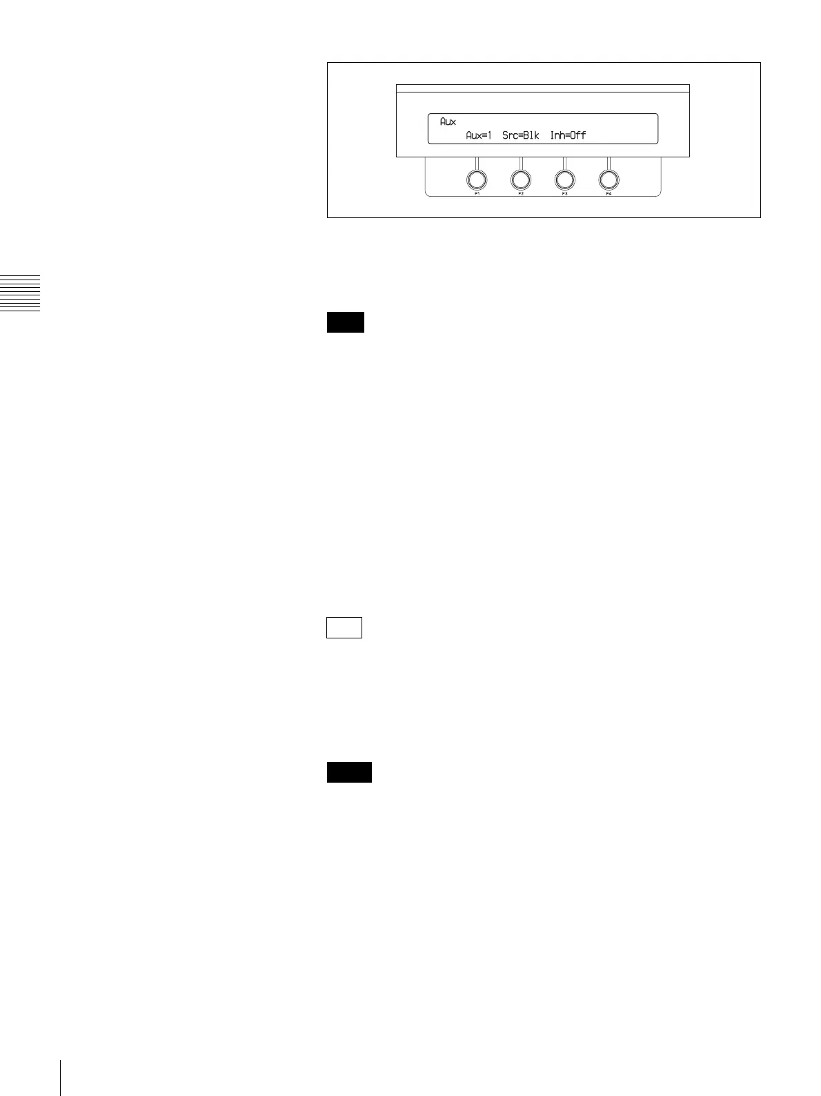
When using the BKDF-901: Rotate the F1 knob to select an output, from
AUX1 to AUX10.
When using the BKDF-902: Skip to step 3.
AUX3 to AUX10 are available only when optional expansion boards are
installed. For details, see page 39.
3
Rotate the F2 knob to select the signal to assign.
BLK: Black signal
IN01 to IN24: Video inputs
STL01 to STL04: Still images 1 to 4 stored in the processor unit
MAT1 to MAT4: Color matte signals 1 to 4
MV1 and MV2: Multi-view output
PGM: Program output
PVW: Preview output
CLN: Clean output (program output without downstream key)
KOut: Key output
MPGM: M/E output (when using the BKDF-902)
MPVW: M/E preview output (when using the BKDF-902)
• If, after step 3, you rotate the F3 knob to set the Inh (Inhibit) item to On,
the AUX output signal cannot be changed from the control panel. Control
is possible only by remote control from an optional AUX BUS remote
controller.
• For more information about screen settings for multi-view output, see
page 96.
• When optional input expansion boards have been installed, signal names
corresponding to the installation positions appear for IN09 to IN24. For
details, see page 39.
• When the display names of input signals or internal signals have been
changed (see page 74), the user-specified names appear.
4
When HD-SDI or SD-SDI signals are being input, rotate the F4 knob to
select whether to output ancillary data (audio, timecode, etc.).
Off: Do not output ancillary data in the input signals.
On: Output ancillary data in the input signals.
Note
Tips
Notes

 Loading...