8
Chapter 1 Overview
4 RGB INPUT connectors (BNC type)
RGB and sync signals can be fed in these connectors.
The type of signal applied to each connector is set with
the INPUT CONFIGURATION menu. Input the
composite sync signals to the HD/COMP connector.
For the separate signals, input the horizontal sync
signals to the HD connector and the vertical sync
signals to the VD connector.
For information about the INPUT CONFIGURATION
menu, see “ [C1] Setting the Input Configuration (SET UP
1) — INPUT CONFIGURATION Menu” on page 28.
5 HD-SDI I/O connectors (BNC type)
HD serial digital signals can be fed in these
connectors. For the 1080/24P (4:4:4), 1080/60I
(4:4:4) and 1080/60P (4:2:2) signals, LINK A and B
are used as the serial digital interface (dual link). For a
single link, line 1 or 2 is used. The type of signal
applied to each connector is set with the INPUT
CONFIGURATION menu. The MONITOR OUT
connectors are used for loop-through output of each
input signal.
Notes
•The MONITOR OUT signals are available only when
the power of the video monitor is turned on. The
MONITOR OUT signals are not available when the
monitor is in standby mode.
•The MONITOR OUT signals do not satisfy the ON-
LINE signal specifications.
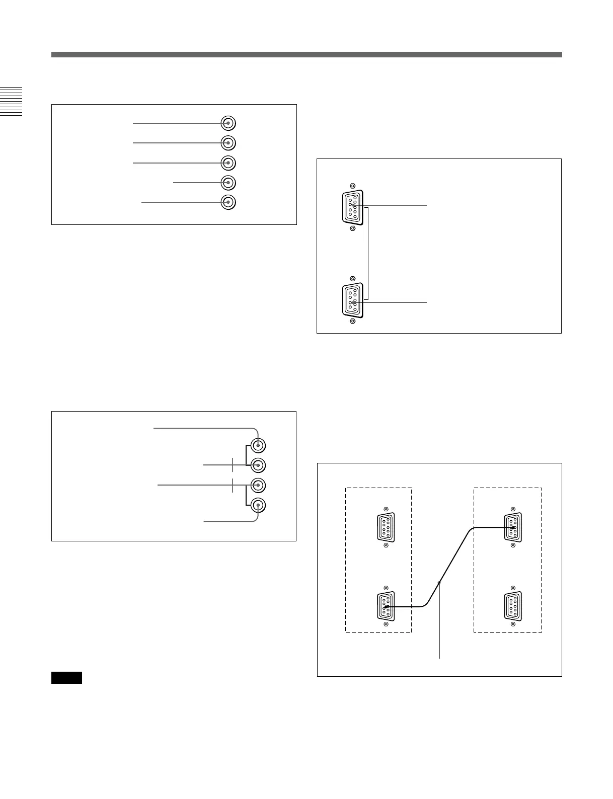
REMOTE 1
IN
OUT
6 REMOTE 1 connectors (female, D-sub 9-pin)
These are RS-485 serial interface connectors, used for
connecting two or more BVM-F24, BVM-Dxx and
BVM-xxE/F/G series monitors.
The IN and OUT connectors form a loop-through
connection.
Connect two monitors using a cable with D-sub 9-pin
plugs such as an RCC-5G (not supplied) as shown in
the figure.
[LINK A] 1
MONITOR
OUT
[LINK B] 2
DUAL LINK
MONITOR
OUT
IN
IN
G
B
R
HD/COMP
VD
Cable with D-sub 9-pin plugs (not supplied)
Monitor 1
Monitor 2
REMOTE 1 IN connector
REMOTE 1 OUT connector
G connector
B connector
R connector
VD connector
HD/COMP connector
LINK A [1] IN connector
LINK A [1] MONITOR OUT connector
LINK B [2] IN connector
LINK B [2] MONITOR OUT connector
For information about the INPUT CONFIGURATION
menu, see “ [C1] Setting the Input Configuration (SET UP
1) — INPUT CONFIGURATION Menu” on page 28.
Location and Function of Parts
REMOTE 1
IN
OUT
REMOTE 1
IN
OUT
 Loading...


