435
selected page number and name, and the lower right
side shows a list of assignable functions.
2
In the <Bank Select> group, select the target bank to
set.
3
Select the target page to set.
4
Press the target button to make an assignment.
5
In the list on the right, select the function to assign.
Set the numerical value of the “?” part of the function
name using the following parameters.
a) The parameters will vary depending on the selected function name.
6
Press [Set].
To release the assignment
Select the target button to release, then press [Clear].
To return button assignments to the defaults
Press [Default Recall], check the message, then press
[Yes].
The button assignments on all pages (1 to 14), including
the Jump Page Assign menu (7326.17) settings, are
returned to the defaults.
To rename a page
1
Select the target page number to set, and press [Page
Name].
2
Enter a name of up to 12 characters in the keyboard
window, and press [Enter].
Lower case characters may be entered, but the entered
characters are displayed as upper case characters on
the buttons in the cross-point pad.
About re-entry button assignment
The following re-entry buttons can be assigned to buttons
on the cross-point pad.
• ROW-n P/P OUT1, ROW-n M/E-1 OUT1 to ROW-n
M/E-5 OUT1 (n = 1 to 4)
• ROW-n P/P OUT6, ROW-n M/E-1 OUT6 to ROW-n
M/E-5 OUT6 (n = 1 to 4)
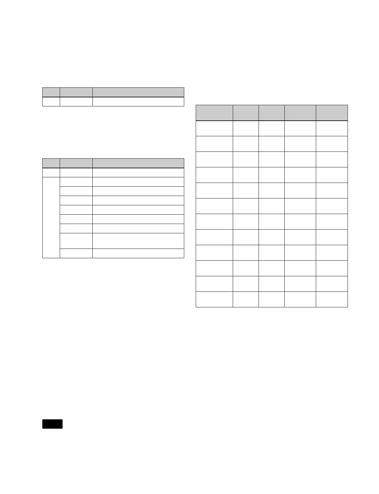
The button numbers and video/key pair numbers of re-
entry buttons is fixed to the following.
The re-entry video/key numbers are set as the pair numbers
by default. Use the defaults as-is, since changing the
settings will make it impossible to select the correct
signals.
Setting the HOME page of the cross-point
pad
This sets the page that is displayed when the [HOME]
button on the cross-point pad is pressed.
1
In the <Bank Select> group of the Engineering Setup
>Panel >Operation >Xpt Module Operation menu
(7326.12), select the target bank to set.
2
In the <Xpt Pad> group, press [Home Page Set].
No. Parameter Adjustment
1 Page Page selection
No. Parameter Adjustment
3 Row Button row selection
4
a)
Key Key selection
Aux AUX bus selection
DME DME channel selection
Util/Sbox Utility/shotbox bank selection
Macro Macro register selection
Mode Display mode selection
Level
Button
Level selection button selection
Table Cross-point assign table selection
Note
Button name
(n = 1 to 4)
Button
number
V/K pair
number
V default
setting
K default
setting
ROW-n P/P
OUT1
284 211 P/P OUT1 P/P OUT1
ROW-n
M/E-1 OUT1
281 221 M/E-1
OUT1
M/E-1
OUT1
ROW-n
M/E-2 OUT1
282 231 M/E-2
OUT1
M/E-2
OUT1
ROW-n
M/E-3 OUT1
283 241 M/E-3
OUT1
M/E-3
OUT1
ROW-n
M/E-4 OUT1
285 251 M/E-4
OUT1
M/E-4
OUT1
ROW-n
M/E-5 OUT1
286 261 M/E-5
OUT1
M/E-5
OUT1
ROW-n P/P
OUT6
294 216 P/P OUT6 P/P OUT6
ROW-n
M/E-1 OUT6
291 226 M/E-1
OUT6
M/E-1
OUT6
ROW-n
M/E-2 OUT6
292 236 M/E-2
OUT6
M/E-2
OUT6
ROW-n
M/E-3 OUT6
293 246 M/E-3
OUT6
M/E-3
OUT6
ROW-n
M/E-4 OUT6
295 256 M/E-4
OUT6
M/E-4
OUT6
ROW-n
M/E-5 OUT6
296 266 M/E-5
OUT6
M/E-5
OUT6

 Loading...