479
GPI Output Settings
Configure the trigger type and other settings for each GPI
output.
GPI output via a network
On GPI outputs via a network, GPI control is performed
using serial tally protocol commands.
GPI outputs can be configured in the same way as parallel
output ports.
• To use GPI via a network, configuration of the SIU
utility connector is required. For details, refer to the
ICP-X7000 Installation Manual.
• This uses a SIU serial tally port, hence the network port
must be configured for a serial tally port.
For details, see “Serial Tally Settings” (page 492).
Configuring GPI Outputs
1
In the Engineering Setup >DCU >GPI Output Assign
menu (7354), select the target GPI output to set.
2
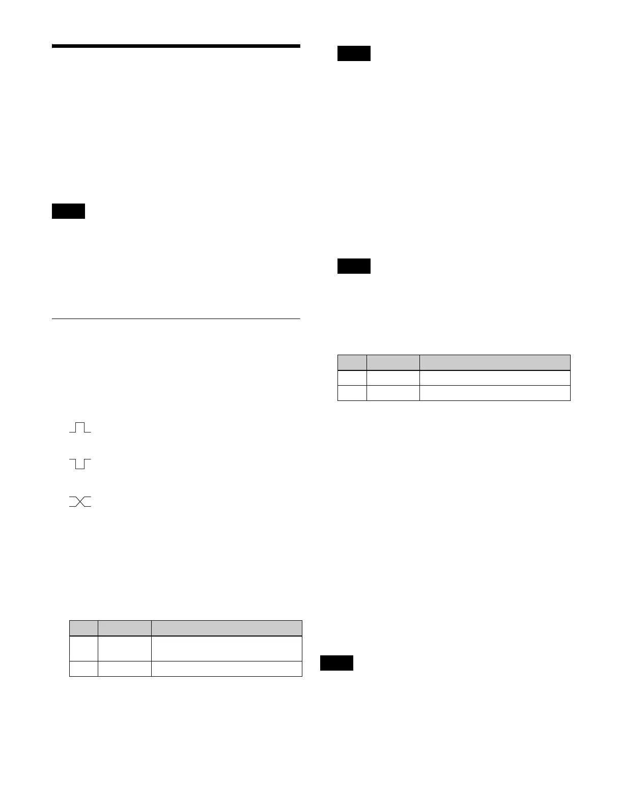
In the <Trigger Type> group, select the trigger
polarity.
(Rising Edge): Trigger causes the relay to open
or the output to go high level, and holds this state
for the pulse width duration.
(Falling Edge): Trigger causes the relay to close
or the output to go low level, and holds this state
for the pulse width duration.
(Any Edge): When a trigger occurs, the relay
opens/closes or the output goes high/low level,
switching state.
Status: The relay opens/closes or the output goes
high/low level in response to the status.
NOP (No Operation): The trigger has no effect on the
relay state or the output level.
3
Set the pulse width and timing.
a) 1: Field 1, 2: Field 2, 3: Any
When “Any Edge” is selected as the trigger type, only
the [Timing] parameter is available. When “Status” is
selected as the trigger type, there are no parameter
settings.
4
In the <Source Device> group, select the control panel
to handle the GPI output.
PNL1: ID1 control panel
PNL2: ID2 control panel
PNL3: ID3 control panel
When the action set in step 5 is executed on the control
panel selected in this step, GPI output occurs. It is also
possible to output error information.
For GPI output via a network, SIU1 must be
configured to use [PNL1], and SIU2 must be
configured to use [PNL2]. [PNL3] cannot be used.
5
Select the action to set.
6
Press [Action Set].
Trigger type and actions list
1)
• When the trigger type is other than “Status”
M/E-x Keyx SS ? Recall, P/P Keyx SS ? Recall, No
Action
• When the trigger type is “Status”
M/E-x Keyx SS ? Recall, P/P Keyx SS ? Recall, M/E-x
Keyx On, P/P Keyx On, Error Make, Error Break, Keep
Make, Keep Break, Device Recording, PREFS 1 to
PREFS 16, No Action
1) M/E-x: where x is the M/E number (1 to 5)
Keyx: where x is the key number (1 to 8)
Testing trigger output
In the Engineering Setup >DCU >GPI Output Assign
menu (7354), press [Test Fire].
This outputs a trigger from the selected output port.
This is no output when the trigger type is “Status.”
Notes
No. Parameter Adjustment
3Pulse
Width
Pulse width
4 Timing Output timing
a)
Note
Note
No. Parameter Adjustment
2 Action Action selection
5 Reg No Register number
Note
 Loading...