2 Product Description User Manual
LED Color State Definition
Gray
OFF Both the AC and DC sides are powered down.
WARNING
Voltage may still be present in AC side circuits after the indicator is off. Pay attention
to the electricity safety when operating.
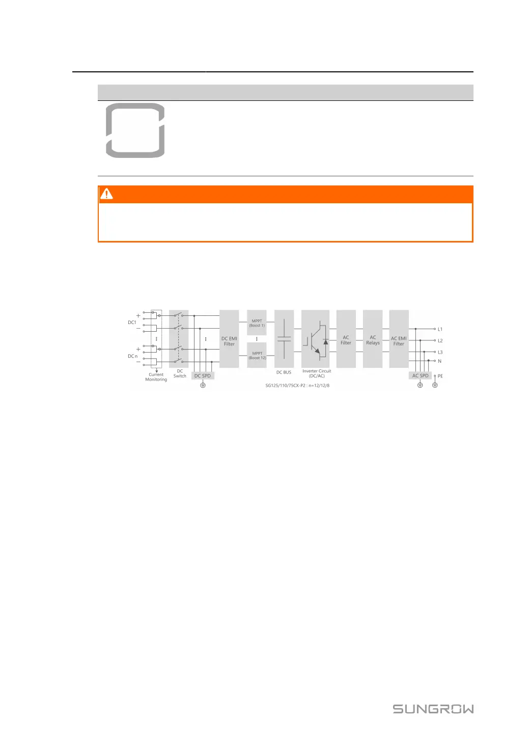
2.5 Circuit Diagram
The following figure shows the main circuit of the inverter.
figure 2-4 Circuit Diagram
•
DC Switches can safely disconnect the PV input when necessary to ensure the safe oper
ation of the inverter and the safety of personnel.
•
The DC SPD provides a discharge circuit for the DC side overvoltage to prevent it from
damaging the internal circuits of the inverter.
•
EMI filters can filter out the electromagnetic interference inside the inverter to ensure that
the inverter meets the requirements of electromagnetic compatibility standards.
•
The MPPT is used to ensure a maximum power from PV arrays at different PV input con
ditions.
•
The Inverter Circuit converts the DC power into grid-compliant AC power and feeds it into
the grid.
•
The AC filter filters the output AC component of high frequency to ensure that the output
current meets the grid requirements.
•
The AC relay isolates the AC output of the inverter from the grid, making the inverter safe
from the grid in case of inverter failure or grid failure.
•
The AC SPD provides a discharge circuit for the AC side overvoltage to prevent it from
damaging the internal circuits of the inverter.
12
 Loading...