5 Electrical Connection User Manual
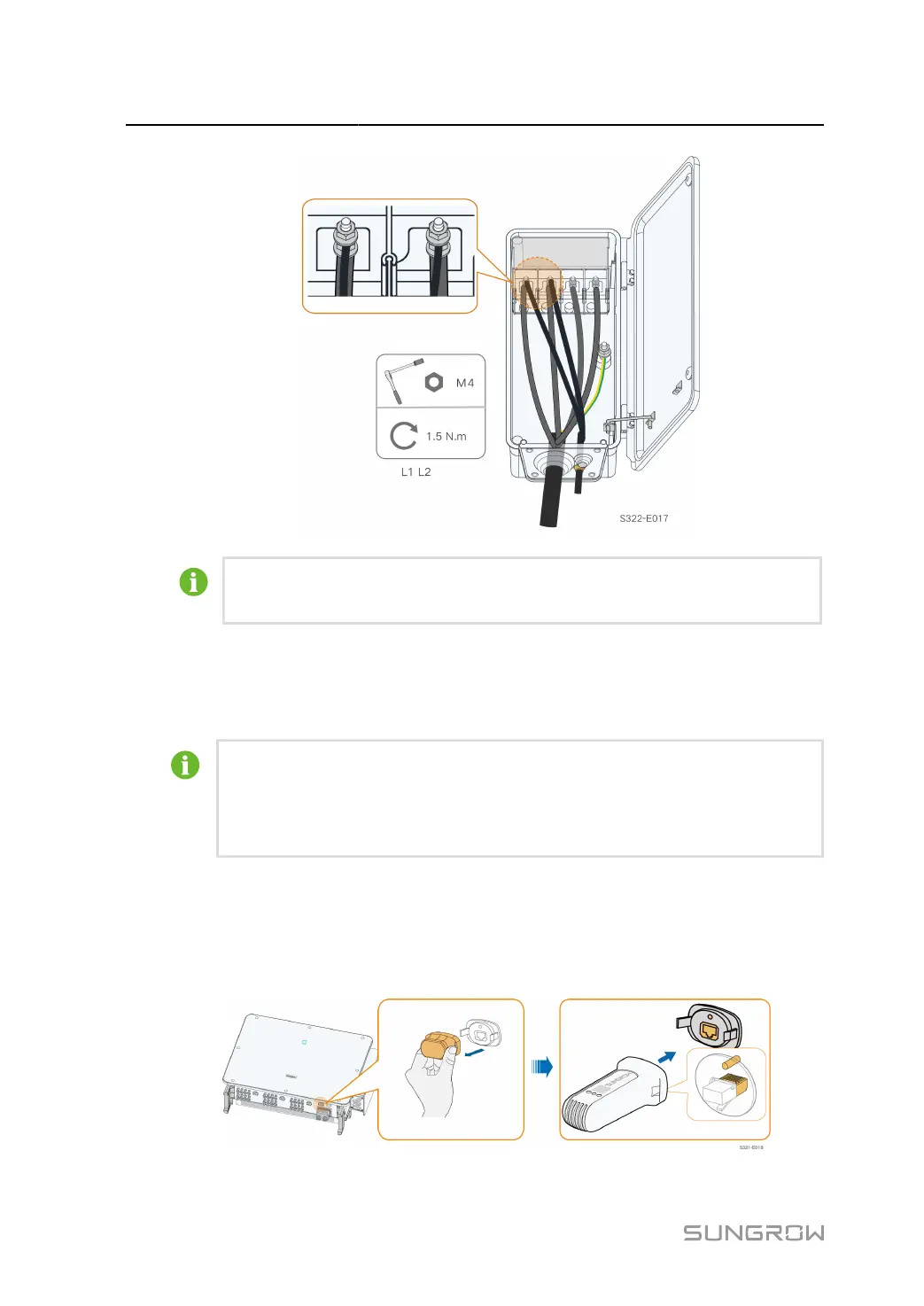
The power cables for tracking system can be connected to any two phases among L1,
L2, and L3.
step 5 Close the protective cover. Close the junction box and tighten the two screws on the front cover
using the supplied hexagon socket wrench.
- - End
The isolation switch (≥400V) and the fuse (16A, gM class) are needed between the
inverter and tracking system control box for protection.
The length of the cable between the internal connection terminals of the inverter and
the fuse is no more than 2.5m.
5.9 Wireless Communication Module Connection(optional)
Install the wireless communication module to the communication interface with a silk screen
of COM3 at the bottom of the inverter.
64
 Loading...