5 Electrical Connection User Manual
WARNING
The external protective grounding terminal must meet at least one of the following
requirements.
• The cross-sectional area of the grounding cable is not less than 10 mm
2
for copper
wire or 16 mm
2
for aluminum wire. It is recommended that both the external protec
tive grounding terminal and the AC side grounding terminal be reliably grounded.
• If the cross-sectional area of the grounding cable is less than 10 mm
2
for copper
wire or 16 mm
2
for aluminum wire, ensure that both the external protective ground
ing terminal and the AC side grounding terminal are reliably grounded.
The grounding connection can be made by other means if they are in accordance with
the local standards and regulations, and SUNGROW shall not be held liable for the
possible consequences.
5.5.1 External Protective Grounding Requirements
All non-current carrying metal parts and device enclosures in the PV power system should be
grounded, for example, brackets of PV modules and inverter enclosure.
When there is only one inverter in the PV system, connect the external protective grounding
cable to a nearby grounding point.
When there are multiple inverters in the PV system, connect the external protective ground
ing terminals of all inverters and the grounding points of the PV module brackets to ensure
equipotential connections to ground cables (according to the onsite conditions).
5.5.2 Connection Procedure
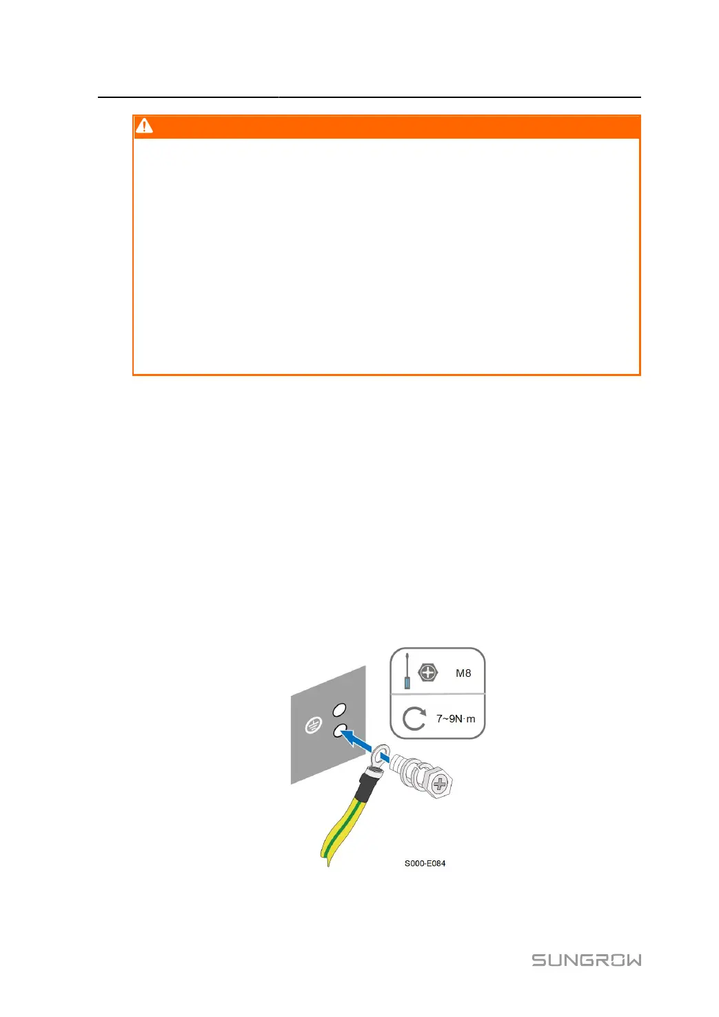
step 1 Prepare the cable and OT/DT terminal, refer to Crimp OT/DT terminal.
step 2 Remove the screw on the grounding terminal and fasten the cable with a screwdriver.
44
 Loading...