User Manual 2 Product Introduction
7
2.2 Product Description
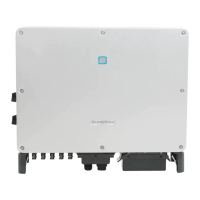
2.2.1 Product Appearance
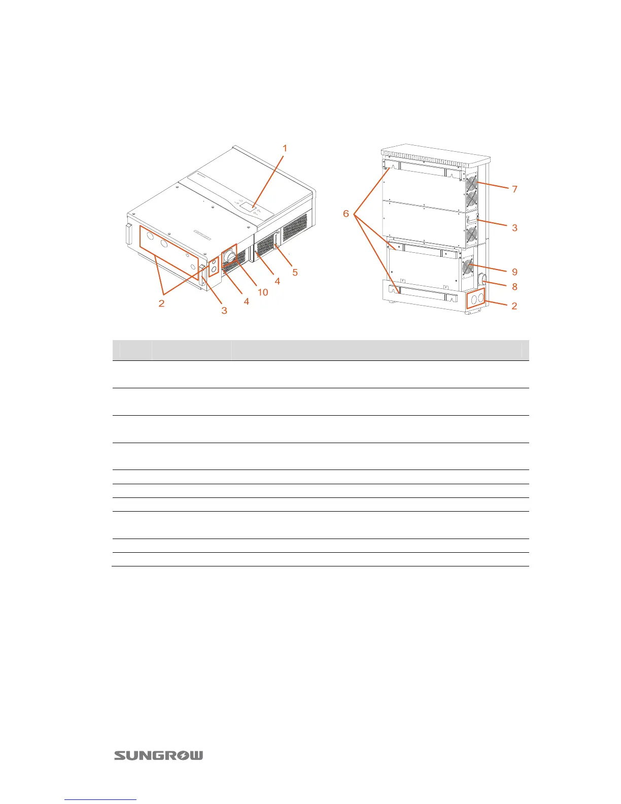
Fig. 2-2 Product Components Description
Item Name Description
1
LCD display
panel
Inverter operation data viewing and parameters
configuration can be performed via the LCD display panel.
2
Connection
openings
Connection openings with plastic threaded plugs for
connecting conduits.
3 Handles
The handles are designed for holding the unit when
transporting, installing or servicing.
4
Second PE
Terminals
Second protective earth terminals as specified in EN 50178.
5 Air outlet Exit of hot air during the inverter operation.
6 Mounting ear It is used for hanging inverter onto the backplate.
7 Fans There are four fans to perform controlled forced-air cooling.
8 DC switch
During normal operation it is in “ON” state. It can shut down
the inverter immediately in “OFF” position.
9 Air inlet Entrance of cool air.
10 AC switch Serviced as an automatic overcurrent device.
 Loading...