User Manual 10 Operation of LCD Display
71
10.3 Main Screen
If the inverter succeeds in commissioning, LCD display will enter into the main
screen, as shown in Fig. 10-2.
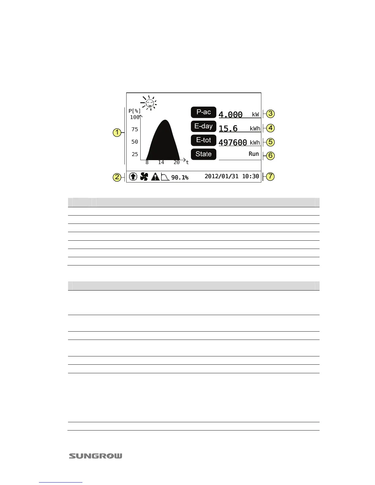
Fig. 10-2 Main Screen Description
No. Description
1 Power curve. x-axis: time in hours; y-axis: output power yield Pin %.
2 Icons (refer to the Tab. 10-3) and the Inverter active power limits (P-W limits).
3 Current output power.
4 Energy generation during this day until now.
5 Total energy generation since initial commissioning.
6 Inverter state.
7 Date (year/month/date) and time.
Tab. 10-2 Inverter State Description
Inverter State Description
Run
After being energized, the inverter tracks the PV arrays’ maximum
power point (MPP) and feeds AC power to grid. This mode is the
normal mode.
Standby
Inverter will enter into Standby mode for insufficient input power.
In this mode the inverter will wait until the DC voltage recovers.
Stop The inverter is shut down.
Key-stop
The inverter will stop operation by manual “Stop” through LCD
menu.
Start The inverter is initializing and synchronizing with the grid.
Upd fail IAP (In Application Programming) update fails
Fault
If a fault occurs, the inverter will automatically stop operation,
trigger the AC relay and show “Fault” on the LCD with the “FAULT”
indicator lit.
Once the fault is removed in recovery time (set by user, see “10.10
Running Parameters Setting”), the inverter will automatically
resume running.
Warning Inverter has checked out some warning information.
 Loading...