User Manual 6 Electrical Connection
39
6.4.1 PV Inputs Configuration
The inverter has two PV input areas DC1 input and DC2 input, each owning its MPP
tracker.
The two PV inputs can be configured in independent mode or parallel mode.
PV Configuration Mode- Independent Mode
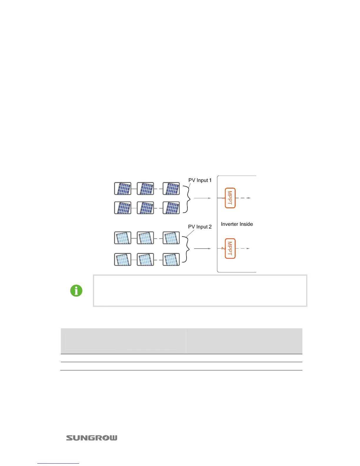
For independent mode, the two PV inputs work independently, each with its own
MPPT. Therefore the two PV inputs can be different with each other, including
different PV module types, different numbers of connected in PV string, different tilt
angles or orientation angle of PV modules.
As shown in the following diagram, the inverter should choose independent mode
due to different orientation angle between the two PV inputs.
To make sure maximum DC power can be utilized, PV strings connected to
individual input area should have a homogenous structure, including the
same type, the same number, identical tilt and identical orientation.
Prior to connecting the inverter to PV inputs, the following electrical specifications
must be met simultaneously:
Total DC Power
Limit
DC Power Limit
for Each Input
Open-circuit
Voltage Limit for
Each Input
Short-circuit
Current Limit for
Each Input
42000W 21000W 1000V 60A
50400W 25200W 1000V 60A
Considering the negative voltage temperature coefficient of PV module, more
attention should be paid to the open-circuit voltage of PV strings when designing at
the lowest ambient temperature.
 Loading...