6-20 ELECTRICAL SYSTEM
STARTER SYSTEM AND SIDE-STAND IGNITION INTERLOCK
SYSTEM
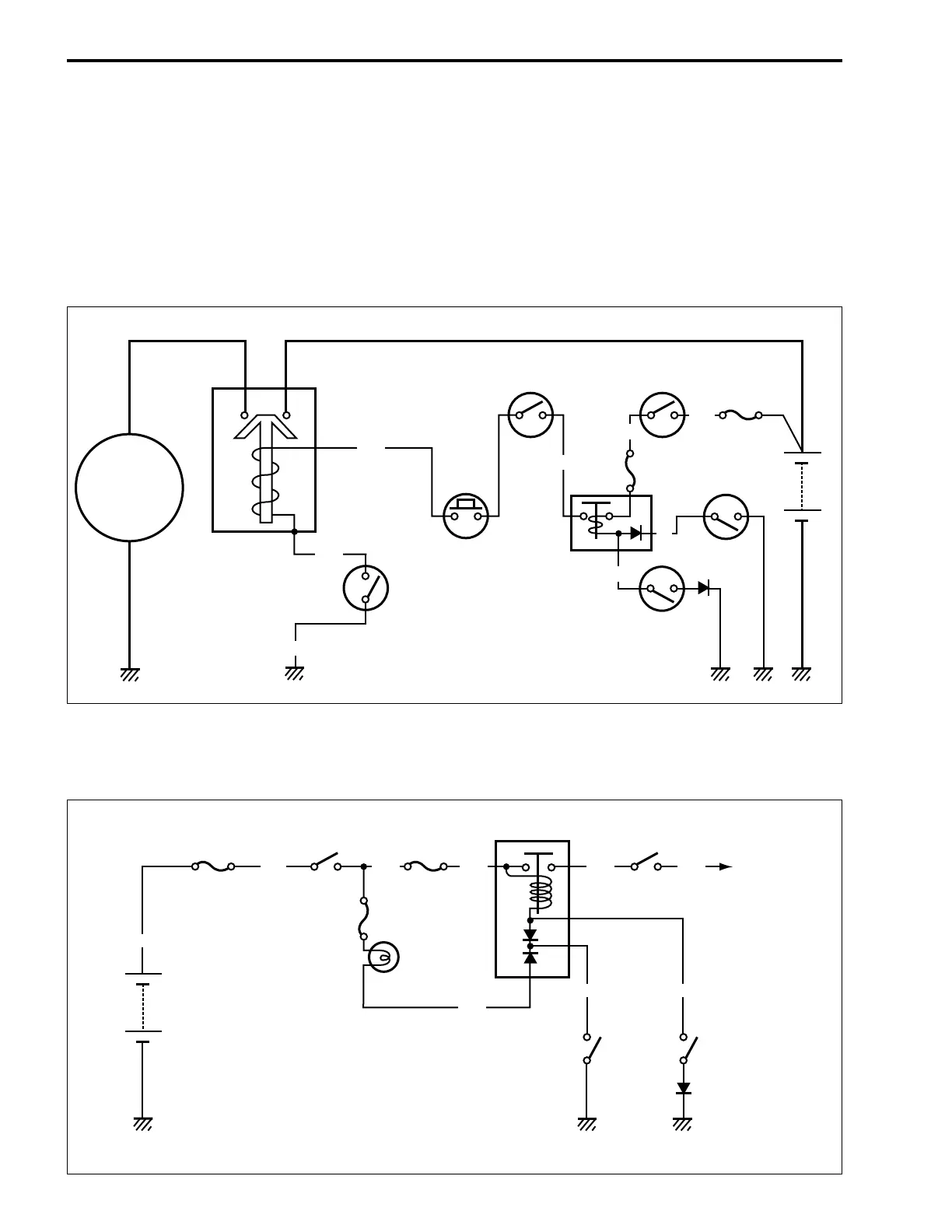
STARTER SYSTEM DESCRIPTION
The starter system consists of the following components: the starter motor, starter relay, clutch lever position
switch, turn signal/side-stand relay, side-stand switch, gear position switch, starter button, engine stop
switch, ignition switch and battery. Pressing the starter button (on the right handlebar switch) energizes the
starter relay, causing the contact points to close, thus completing the circuit from the starter motor to the bat-
tery. The starter motor draws about 80 amperes to start the engine.
SIDE-STAND/IGNITION INTERLOCK SYSTEM DESCRIPTION
This side-stand/ignition interlock system prevents the motorcycle from being started with the side-stand
down. The system is operated by an electric circuit provided between the battery and ignition coil.
B/Bl
Bl/B
Bl
G
B/O
B/R
Starter
motor
Ignition
switch
Fuse (30 A)
Side-stand
switch
Starter relay
Engine stop
switch
Starter
button
Turn signal/
side-stand relay
Fuse
(15 A)
Gear
position
switch
Battery
Clutch lever
position switch
B/W
B/Y
B/Bl B/R
R
Bl
G
Bl/B
B/O
O/Y
Fuse (30 A)
Side-stand
switch
Turn signal/
side-stand relay
Fuse
(15 A)
Fuse
(15 A)
Battery
Ignition
switch
Engine stop
switch
Neutral
indicator light
Gear
position
switch
To ignitor
and ignition
coil
B/R
WIRE COLOUR
Bl: Blue B/Bl: Black with Blue tracer
G: Green B/O: Black with Orange tracer
O: Orange B/R: Black with Red tracer
R: Red Bl/B: Blue with Black tracer
O/Y: Orange with Yellow tracer

 Loading...


