ELECTRICAL SYSTEM 6-27
SIDE-STAND/IGNITION INTERLOCK
SYSTEM PART INSPECTION
Check the interlock system for proper operation. If the interlock
system does not operate properly, check each component for
damage or abnormalities. If any abnormality is found, replace
the component with a new one.
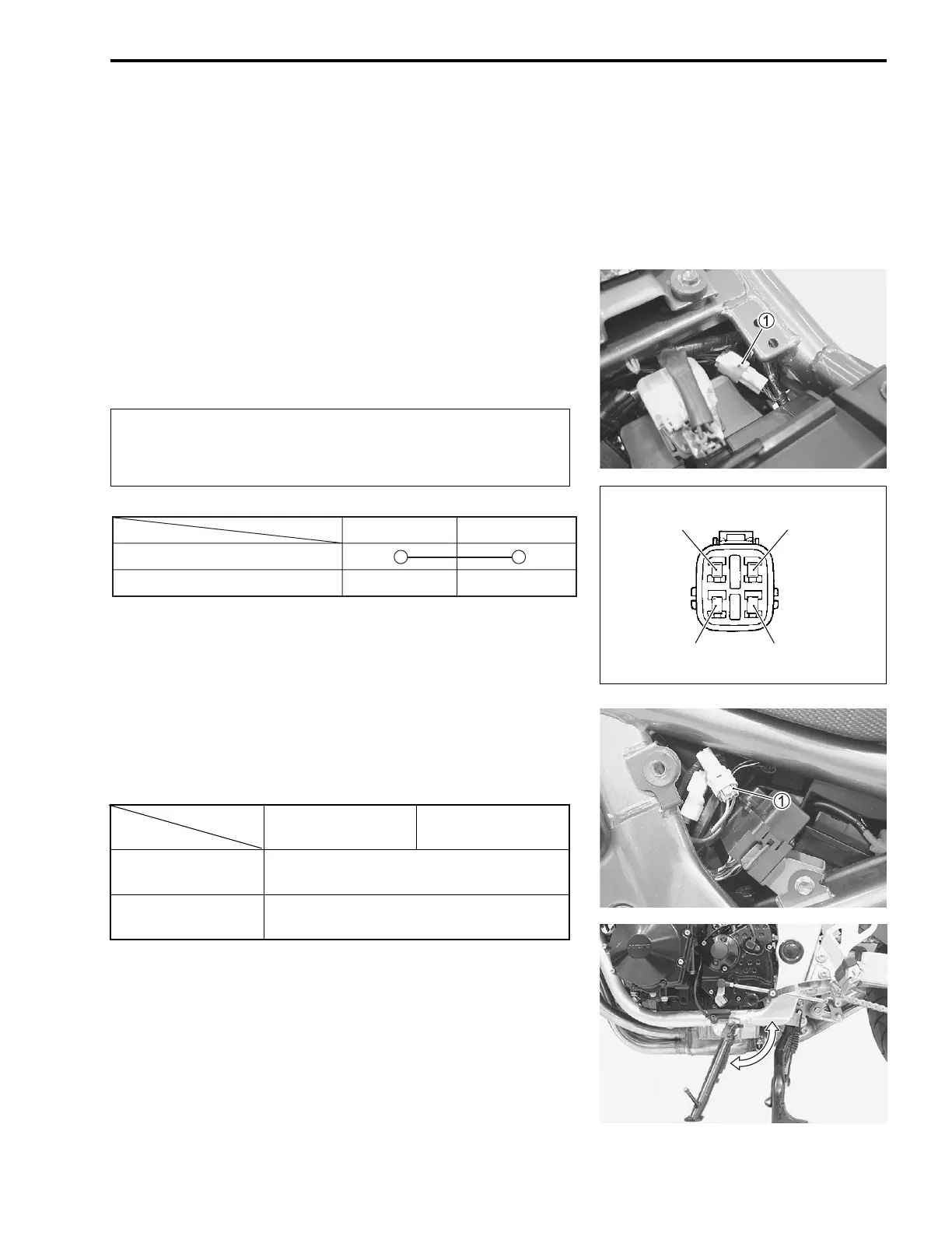
GEAR POSITION SWITCH
• Remove the seat. (!5-4)
• Disconnect the gear position switch coupler
1 and measure
the continuity between Bl and B/W with the transmission in
neutral.
#
" 09900-25008: Multi circuit tester set
* Tester knob indication: Continuity test (+)
SIDE-STAND SWITCH
• Remove the frame cover (LH). (!5-4)
• Disconnect the side-stand switch coupler
1 and measure the
voltage between Lg and B/W lead wires.
" 09900-25008: Multi circuit tester set
, Tester knob indication: Diode test (-)
NOTE:
If the tester reads 1.4 V and below when the tester probes are
not connected, replace its battery.
When disconnecting and connecting the gear position
switch coupler, make sure to turn off the ignition
switch, or electronic parts may get damaged.
Lg
(
+ probe)
B/W
(
- probe)
ON
(side-stand up)
0.4 – 0.6 V
OFF
(side-stand down)
1.4 V and more
(Tester’s battery voltage)
ON (Neutral)
Bl B/W
OFF (Except neutral)

 Loading...


