ELECTRICAL SYSTEM 8-29
SPEED SENSOR
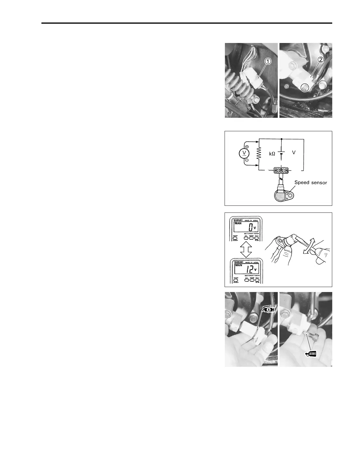
• Remove the left footrest mud guard. (!7-8)
• Disconnect the speed sensor lead wire coupler
1.
• Remove the speed sensor
2.
• Connect
- terminal to ground terminal and
+ to the Vcc ter-
minal.
• Connect 1 kΩ resistor, 12 V battery and the multi circuit tester
as shown.
# 09900-25008: Multi circuit tester set
( Tester knob indication: Voltage (%
%%
%)
Under above condition, when a suitable screwdriver touching
the pick-up surface of the speed sensor moves, the tester read-
ing voltage relatively changes (0 V → 12 V or 12 V → 0 V). If the
tester reading voltage does not change, replace the speed sen-
sor with a new one.
NOTE:
The highest tester reading voltage (12 V) while testing is same
as the total voltage of four batteries.
• Apply SUZUKI SUPER GREASE “A” to the speed sensor O-
ring before installing it.
. 99000-25030: SUZUKI SUPER GREASE “A” (USA)
99000-25010: SUZUKI SUPER GREASE “A” (Others)
• Apply THREAD LOCK SUPER “1303” to the speed sensor
mounting bolt
3.
• Tighten the speed sensor mounting bolt to the specified
torque.
3 99000-32030: THREAD LOCK SUPER “1303”
4 Speed sensor mounting bolt: 10 N·m (1.0 kgf-m, 7.0 lb-ft)
1
12
R/B
P
B/W

 Loading...