4-38 DRIVE TRAIN
SHIM ADJUSTMENT
BACKLASH
• Install the pinion gear assembly, removed shim(s) and new
bearing locknut. (!4-32)
• Tighten the bearing locknut to the specified torque. (!4-32)
NOTE:
At this time, it is not necessary to stake the bearing locknut.
(!4-32)
• Install the removed left side shim(s) and ring gear. (!4-33)
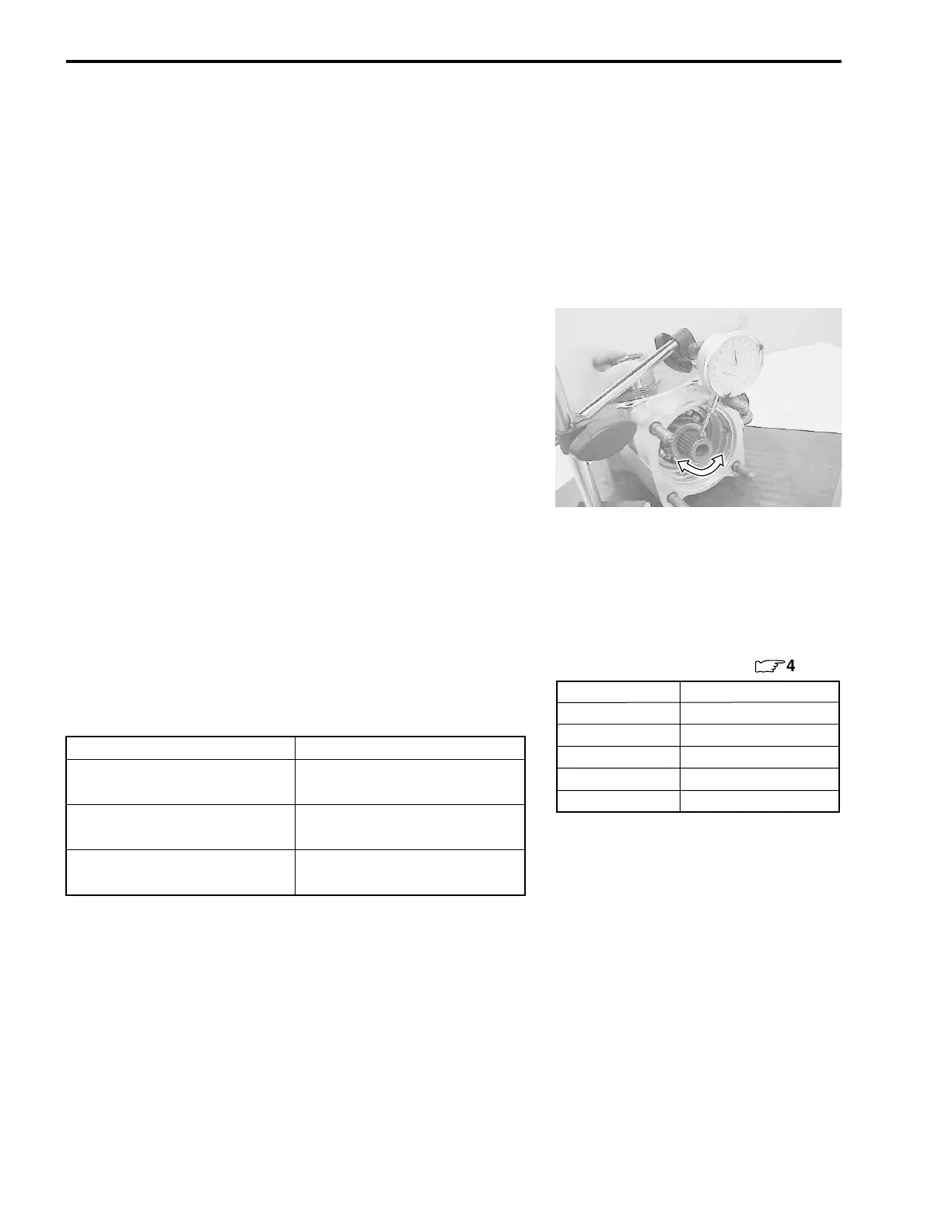
• Measure the backlash using the dial gauge, as shown. Take
backlash readings at several places while turning the pinion
gear shaft in each direction and securely holding the ring
gear. If the backlash is not within specification, the shim must
be changed and the backlash should be re-checked until cor-
rect. Refer to the chart at the right for the appropriate shim
thickness.
* Backlash
Standard: 0.02 – 0.06 mm (0.0008 – 0.0024 in)
........... Without gear case cover
specification
0.08 – 0.13 mm (0.0031 – 0.0051 in)
........... Gear case cover assembled
specification
NOTE:
Adjust the backlash by referring to the chart at the right and
using the thickness of the removed shims as a guide.
0
Backlash Shim adjustment
Under 0.02 mm
(0.0008 in)
Increase shim thickness
0.02 – 0.06 mm
(0.0008 – 0.0024 in)
Correct
Over 0.06 mm
(0.0024 in)
Decrease shim thickness
Part No.
Shim thickness
For left side of ring gear (
:
4-40)
27326-09F70-030 0.30 mm (0.0118 in)
27326-09F70-035 0.35 mm (0.0138 in)
27326-09F70-040 0.40 mm (0.0157 in)
27326-09F70-050 0.50 mm (0.0197 in)
27326-09F70-060 0.60 mm (0.0236 in)

 Loading...