20
| Instructions for unloading on the site as well as installation and connection
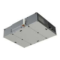
Sections are mounted to base frames with self-drilling screws. In the base frame you will find a sufficient number of 5
mm holes that are prepared for the self drilling screws. In this picture you are standing and you are watching the as-
sembled base frame on the floor or roof.
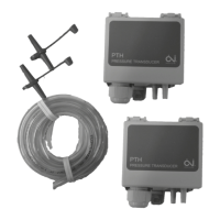
Use self-drilling screws — 4,8 X 18 mm — to be screwed upward through the holes into the bottom profile of the air
handling unit Note! A screw must be placed in every hole to achieve the necessary strength. In this picture you are ly-
ing on the floor or roof looking upward under the base frame. The screws will not be visible, when you are standing be-
side the unit looking at the unit
I.2.8 Joining the AHU sections
The sections must be placed on the base frame and if the unit is delivered with 150 mm legs, the sections must be posi-
tioned directly in line with each other.
Ensure that the internal factory-fitted rubber sealing is undamaged
output |
 Loading...