Instructions for unloading on the site as well as installation and connection |
25
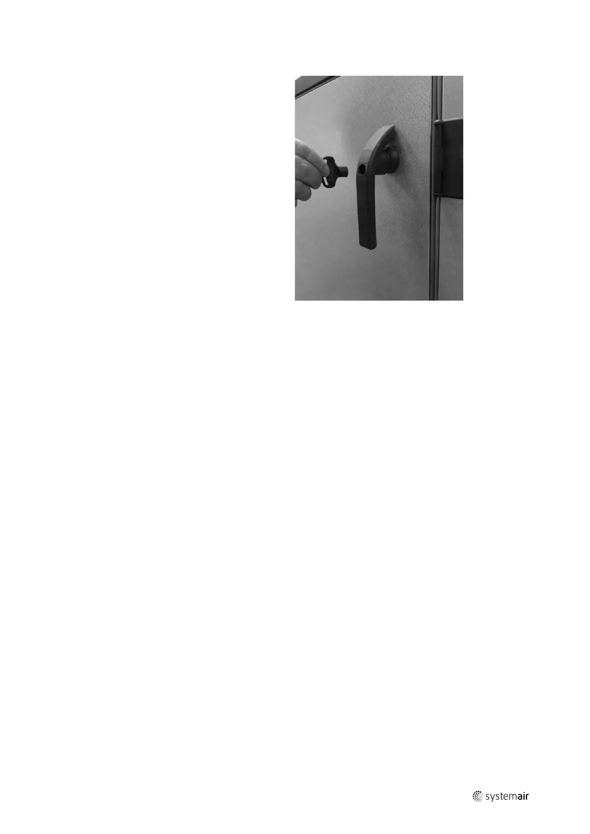
I.2.13 Lock the doors by using the key
Use the key to lock the doors. The doors are not locked
automatically by turning the handle to the vertical
position.
I.3 Installation - electrical
I.3.1 Description
The position of components is shown and described in Annex 2.
Connections to terminals are shown in the wiring diagram.
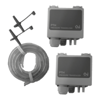
When control of constant pressure in the ducts (also called demand controlled capacity) is required, the pressure trans-
mitters must measure in the duct system at places where all pressure changes can be registered accurately for reliable
pressure control. This placement is left to the customer’s free choice.
It is important to achieve a constant pressure – also for the most faraway diffusers.
I.3.2 Wiring diagrams
The wiring diagrams are printed in separate manuals delivered with the units.
The wiring diagrams are not unique for the order specific units, but it is standard wiring diagrams with data about all
configurations of the units. Hereby the wiring diagrams will inform about components that are not ordered and deliv-
ered. See the order confirmation and Annex 2 with exact information about the accessory components that are ordered
and delivered.
The wiring diagram includes:
• General description, Circuit diagrams, Cabinet layout, Terminal matrix and Cable plan.
• The wiring diagrams are on the DVD delivered with every unit.
I.3.2.1 Geniox units – labels on or with the cabinet
• Label with data about the cabinet – including data about fuses – see chapter D.2.2
• Flowchart – see chapter D.2.3– unique for the order specific unit – printed with the unique production number of the
unit
• Label with terminal plan for external components – see chapter D.2.5– standard, and not unique for the order specific
unit
I.3.3 Installation of mains power supply
An AC/DC residual current device must be installed in the power supply. The power supply for the units is 3*400 V + N
+ PE - 50 Hz. Protection of the units in accordance with the local statutory requirements for the additional protection of
systems with frequency converters and EC fans. The operator is responsible for the installation of the necessary protec-
tion equipment (supply disconnecting device is not delivered by Systemair.
output |
 Loading...