Calibration Procedure—465B
Service
Adjustment Procedure
j.
Set:
ATIME/DIV 2/rs
HORIZ
DISPLAY ALT
k.
CHECK—TRACE
SEP
control will move the B trace
at least ±4
vertical divisions from the A trace when rotating
TRACE
SEP control to fully clockwise and
fully
counterclockwise positions (A trace
centered).
I.
CHECK—B trace moves an equal
distance above
and below the A trace
(«4
divisions).
Below
SN B030000;
ADJUST—Trace Sep
Range Adjust R2035for
±4divisions
of
trace separation when
rotating
TRACE
SEP control to
fully clockwise and fully
counterclockwise positions.
m.
ADJUST—
T
race Sep Centering R2117 sothat
the
B
trace moves
an equal distance above and below the A
Trace
(~4 divisions). Below SN B030000; ADJUST Trace
Sep Comp adjust R2030 for minimum
movement of the A
Trace while rotating
TRACE
SEP
control from fully
clockwise to
fully counterclockwise positions.
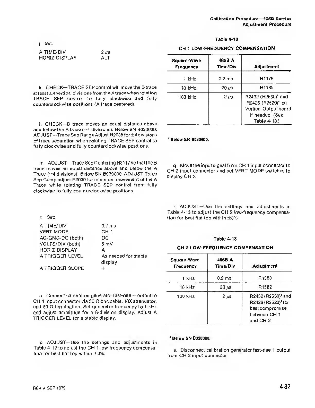
Table
4-12
CH 1
LOW-FREQUENCY COMPENSATION
Square-Wave
Frequency
465 B A
Time/Div Adjustment
1 kHz 0.2 ms
R1176
10 kHz
20
/vs
R1185
100
kHz 2/ys R2432
(R2530)* and
R2426 (R2520)* on
Vertical Output board
if needed. (See
Table
4-13.)
1
Below SN B030000.
q.
Move the input
signal
from
CH
1 input connector to
CH 2 input connector and set VERT MODE switches to
display CH 2.
n.
Set:
A
TIME/DIV
VERT MODE
AC-GND-DC (both)
VOLTS/DI
V
(both)
HORIZ DISPLAY
A
TRIGGER
LEVEL
A TRIGGER SLOPE
0.2
ms
CH 1
DC
5 mV
A
As
needed
for
stable
display
+
o.
Connect calibration generator fast-rise + output to
CH 1 input connector via 50 0 bnc cable,
10X attenuator,
and 50 O termination. Set generator
frequency
to I
kHz
and
adjust amplitude for
a
6-division display. Adjust A
TRIGGER LEVEL for a stable display.
r.
ADJUST
—Use
the
settings and adjustments in
Table
4-13
to adjust the CH
2
low-frequency
compensa-
tion for best flat
top
within ±3%.
Table
4-13
CH 2
LOW-FREQUENCY COMPENSATION
Square-Wave 465B A
Frequency Time/Div
Adjustment
1
kHz 0.2 ms R1580
10 kHz
20/jS R1582
100
kHz
2 (&
I
R2432 (R2530)* and
R2426 (
R2520)*
f or
best compromise
between CH 1
and CH
2.
p.
ADJUST
—Use the settings
and
adjustments in
Table
4-12
to adjust the CH
1
low-frequency compensa-
tion for best flat top within ±3%.
*
Below SN B030000.
s. Disconnect calibration generator fast-rise + output
from CH
2 input connector.
REV
A SEP 1979
4-33

 Loading...


