Calibration
Procedure—465B
Service
Adjustment Procedure
c. Position top of display to top graticule line.
e.
If above checks are within
3%,
proceed to step
17;
if
not, continue with part f.
d.
CHECK—Display compression or expansion is 0.1
division or less.
e. Position bottom of display to bottom graticule line.
f. CHECK—Display compression or expansion is 0.1
division
or
less.
f. Set:
A TIME/DIV
VERT MODE
AC-GND-DC (both)
VOLTS/DIV (both)
A TRIGGER LEVEL
A
TRIGGER
SLOPE
0.2 ms
CH
1,
CH
2,
and ALT
DC
5 mV
As needed for
stable
display
—
(minus)
g.
Set CH
1
VAR VOLTS/DIV control
to
calibrated
detent.
h. Disconnect generator standard-amplitude output
and dual-input coupler.
16. Check/Adjust Low-Frequency Compensation
a. Set:
A TIME/DIV
VERT MODE
AC-GND-DC (both)
VOLTS/DIV (both)
A TRIGGER LEVEL
0.2 ms
CH 1
DC
5 mV
As needed for stable
display.
g.
Unplug
cable connector from J4387 (Vert Alt Sync
pulse) and insert plug into bnc-to-cable-connector
adapter. Connect the square-wave output of
low-
frequency
generator
to
the bnc-to-cable-connector
adapter via a 50
D bnc cable. Set the generator output
frequency
to 1
kHz and adjust CH 1 and CH 2
Vertical
POSITION controls for a 6-division display. Adjust A
TRIGGER LEVEL control for a
stable
display.
Presenta-
tion
will
be a square wave
when
the
CH
1
and CH 2 traces
alternate at the generator frequency.
NOTE
As an alternate signal source,
use the fast-rise
—
(minus) output of the calibration
generator. Do not
terminate the cable and adjust the output amplitude
to maximum.
b.
Connect calibration generator fast-rise + output
to
CH 1 input via
a
50 O bnc cable, 10X attenuator, and 50 Q
bnc termination.
c.
Adjust calibration generator to maintain
a
5-division
display throughout step 16.
d. CHECK—Display overshoot or rounding is within
3% (5
divisions ±0.15 division) for each A TIME/DIV and
generator setting
given
in
Table
4-10.
Table
4-10
MAXIMUM
OVERSHOOT OR ROUNDING
Calibration Maximum
Generator A Time/Div Overshoot or
Signal Setting Rounding in Div
1 kHz .2 ms 4.85 to 5.15
10
kHz
20
pS
4.85
to 5.15
100 kHz
2 A/S
4.85
to 5.15
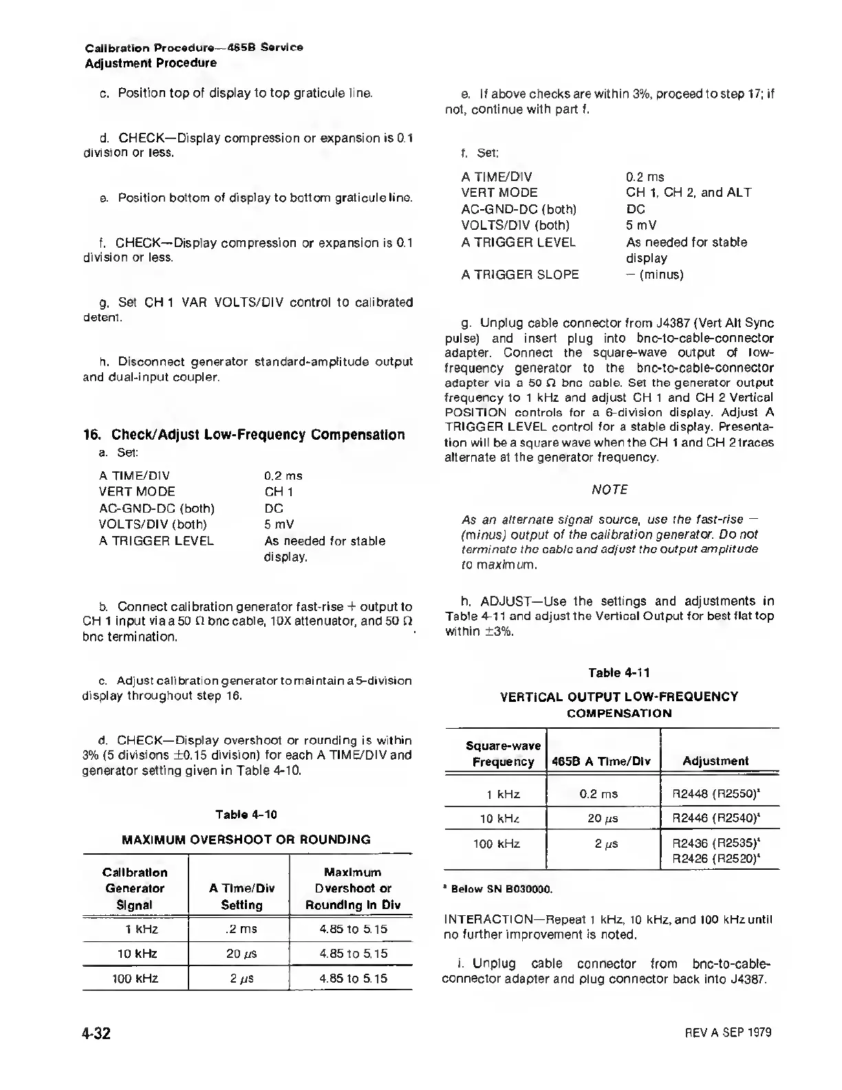
h. ADJUST—Use the settings and
adjustments in
Table
4-1
1 and adjust the
Vertical Output for best flattop
within ±3%.
Table
4-11
VERTICAL OUTPUT
LOW-FREQUENCY
COMPENSATION
Square-wave
Frequency 465B A Time/Div
Adjustment
1 kHz
0.2 ms R2448 (R2550)*
10 kHz
20
ps
R2446 (R2540)*
100
kHz
2 a/S
R2436 (R2535)*
R2426 (R2520)*
*
Below SN B030000.
INTERACTION—
Repeat 1 kHz, 10 kHz, and 100 kHz until
no further improvement is noted.
i. Unplug cable connector
from bnc-to-cable-
connector adapter and plug connector
back
into
J4387.
4-32
REV A SEP
1979

 Loading...


