Theory of
Operation—
465B Service
Power Input
Power is
applied to the
primary of
transformer
T1
4500
through Line Fuse F14500,
POWER switch S14510,
Ther-
mal Cutout SI 4520,
Line Voltage
Selector
switch
S14500,
and the
Regulating Range
Selector
assembly. Line
Voltage Selector
switch SI 4500
connects
the split
primaries
of
T14500
either in
parallel for 115-volt
nominal
operation or in
series for
230-volt nominal
operation. Line
Fuse FI 4500
value is
selected to provide the
required
protection
for each
nominal line voltage.
Refer
to
Replaceable
Electrical
Parts list for correct
fuse
values.
The unused
windings between
pins
10, 11.
and 12 of
T14500
are
intended for use
with the optional
Inverter
Circuit
Board
(Option
07)
or
DM-series Digital
Multimeters.
Option 07 allows
the
instrument
to
be
operated
from an external dc
power source
or an 1106
Power
Supply. Option 07
and the
DM-series Digital
Multimeters
cannot be used at
the same time.
Secondary
Circuit
The
-8
volt,
4
5
volt, +15 volt, and +55
volt power
supplies
are
series-regulated supplies.
U4411A, U4411B,
U4206A, and U4206B
are two-channel,
high-gain amplifier
cells with
differential inputs.
These amplifiers
monitor
voltage
variations in the
output voltages
and supply
correction
information to
the series-regulating
tran-
sistors. The
+55 volt supply is
the source of
the reference
voltage for
the remaining
supplies and its output
must be
correct or the
-8
volt, +5 volt, and
+15 volt supplies
will
not operate
within their limits.
Current-limiting
circuits provide short
circuit protec-
tion
for each of
the regulated
supplies. The
following
description
applies only to
the +55 volt
current limiting
circuit; the
other current-limiting
circuits
operate in
a
similar manner.
In the +55
volt supply, Q4303
is normally biased off.
Linder normal conditions
the base of Q4303 sets at about
+55
volts. Under
conditions
of
power supply loading,
when the
supply current
increases, the
voltage drop
across
R4303 increases.
This
increasing voltage is
coupled through the
base of Q4301 to the
voltage
divider,
comprised of R4302
and R4208, causing
the base of Q4303
to
go
more
positive.
When the supply current
increases
sufficiently, Q4303 turns
on. The collector of
Q4303 moves
in the
negative
direction and begins turning off
Q4302and
Q4301.
Transistor Q4301 will
continue conducting
some
current, even
when the
supply is limited, in
order to
produce
enough voltage
drop across R4303 to
keep Q4303
biased on. The
limited
supply output voltage can be any
value between its
regulated value
and zero,
depending on
the
extra load it is
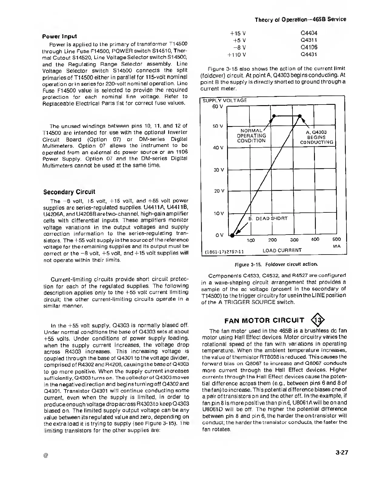
trying to supply (see
Figure
3-15).
The
limiting
transistors for the
other supplies are:
+15 V
Q4404
+5 V
Q4311
-8
V
Q4106
+
110 V
Q4431
Figure
3-15
also
shows the action
of the current
limit
(foldover) circuit. At
point A, Q4303 begins
conducting. At
point B the supply is directly shorted to
ground through a
current
meter.
SUPPLY
VOLTAGE
60 V
50 V
40 V
30 V
20
V
10 V
0 V
MA
(1861-17)2757-11
LOAD
CURRENT
Figure
3-15. Foldover circuit
action.
Components C4533, C4532,
and R4527 are
configured
in a
wave-shaping circuit
arrangement
that provides a
sample of the ac
voltage (present
in the secondary
of
T
1
4500)
to the
trigger circuitry for use in the
LINE position
of
the A
TRIGGER SOURCE switch.
FAN
MOTOR CIRCUIT
The fan motor used
in the 465B is a brushless dc
fan
motor using
Hall
Effect
devices. Motor circuitry
varies the
rotational
speed
of the fan with
variations in operating
temperature.
When
the
ambient temperature increases,
the
value of thermistor RT8038
is reduced. This causes
the
forward bias on
Q8067
to
increase and Q8067
conducts
more
current through the
Hall Effect devices.
Higher
currents through the
Hall Effect devices cause
the poten-
tial difference across
them (e.g., between
pins 6 and
8
of
the
fan) to i ncrease. This
potential difference biases one
of
a pair of
transistors on and the
other
off.
In the
example, if
fan pin 8 is
more positive than pin
6,
U8061Awill be on and
U8061D will be off. The
higher the potential difference
between pin
8
and pin
6,
the
harder the
on
transistor will
conduct;
the harder the
transistor conducts, the
faster the
fan rotates.
3-27

 Loading...


