Section
5—
46SB Service
MAINTENANCE
INTRODUCTION
This section of the
manual contains information
for
use
in
preventive
maintenance, troubleshooting and
correc-
tive
maintenance Procedures
for removal and replace-
ment of the
standard
instrument cabinet and the rack
adapter are presented at
the beginning of the
section.
Should the
instrument require
shipment to
a
Tektronix
Service
Center for repair, refer to
the repackaging instruc-
tions at the end of
this section
CABINET AND RACK ADAPTER
REMOVAL AND
REPLACEMENT
The standard
cabinet protects
the interior of this
instrument from
accumulation of dust and
also provides
protection to
personnel from the
operating
potentials
present In
addition, the cabinet
reduces the emi (elec-
tromagnetic
interference)
radiation from the
instrument
and
interference to the
display due to other
equipment
The
front panel
cover provides a dust-tight
seal around
the front
panel and protects the
front panel when
storing
or transporting
the instrument.
The Rack
Adapter
cabinet for the 465B provides
the
proper
electrical environment for
the
instrument,
reduces
dust
accumulation,
minimizes
handling damage, and
provides a
means for
mounting the
instrument solidly to
a
surface such as a
rack or
console.
Standard
Cabinet Removal
The standard
instrument cabinet
can
be
removed in the
following manner
1. Disconnect the
instrument power cord
from the
power
source.
2. Install the
front panel cover and set
the instrument
face
on
a
flat surface.
1861-2
1
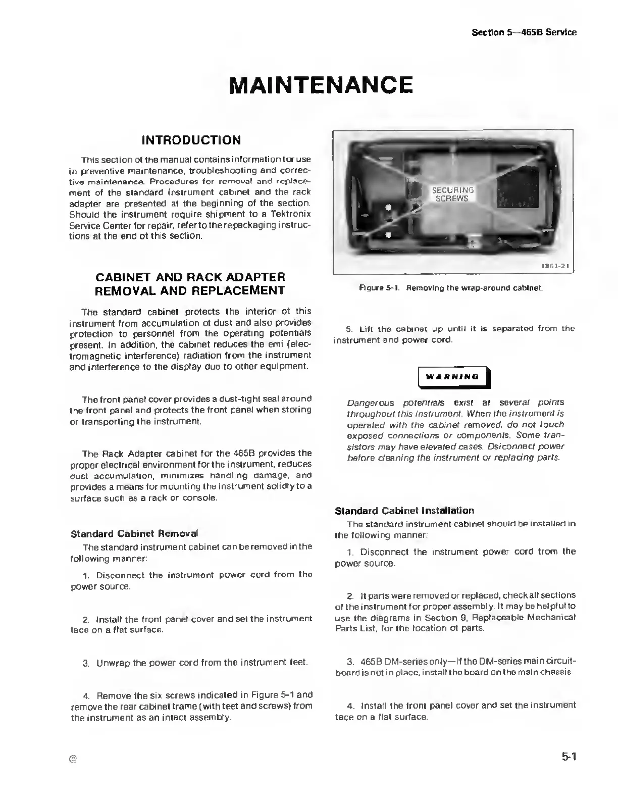
Figure 5-1.
Removing the wrap-around cabinet.
5. Lift the cabinet up
until
it is
separated from the
instrument and power cord
WARNING
Dangerous
potentials exist at several points
throughout this
instrument
When
the instrument is
operated with the cabinet
removed, do not
touch
exposed
connections or components.
Some tran-
sistors may have
elevated cases. Dsiconnect
power
before
cleaning the instrument or
replacing parts.
Standard
Cabinet
installation
The standard
instrument cabinet should he installed in
the
following
manner
1
Disconnect the instrument power
cord from the
power source
2.
If
parts were removed or
replaced, check all
sections
of the
instrument for proper assembly
It may be helpful to
use the diagrams
in Section
9,
Replaceable
Mechanical
Parts List, for the location
of parts
3. Unwrap
the power cord from
the instrument feet
3. 465B
DM-seriesonly— If the DM-series
main circuit-
board is not i n place,
install the board on the
mai n chassis.
4. Remove the
six screws indicated
in Figure
5-1
and
remove the rear
cabinet frame
(with feet and screws) from 4 Install the
front panel cover and set the
instrument
the
instrument as an intact
assembly face on a flat surface

 Loading...


