Operating
Instructions—465B Service
Table
2-3
FUSE SELECTION
Line
Voltage Selector
Switch Position Fuse
Size
115-Volt Nominal 1.5 A, 3AG,
Fast-blow
230-Volt
Nominal 0.75 A, 3AG,
Fast-blow
Instrument Cooling
To maintain adequate
instrument cooling, the
ventila-
tion holes in the
equipment cabinet must remain open,
and
the air filter must be
cleaned or replaced when
it gets dirty.
Rackmounting
For
rackmounting details refer to the
rackmounting
installation
instructions at the end of this
section.
CONTROLS,
CONNECTORS, AND INDICATORS
The major
controls, connectors, and indicators
for
operation of the 465B are located on the front
panel
of
the
instrument. A few auxiliary
functions
are
provided on the
rear panel. Figures
2-3
through
2-7
showthe front and rear
panels of the instrument with the
cunlruls, connectors,
and indicators called out The circled numbers corres-
pond
to
the discussions about particular controls, con-
nectors,
and indicators. If
your
instrument is equipped
with a
DM44 Digital Multimeter, refer
to
either the
465B/DM44
Operators Manual
or
the DM44 Service
Manual for descriptions of
DM44
controls,
connectors,
and indicators.
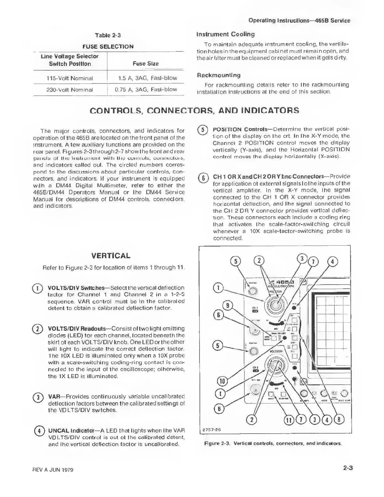
VERTICAL
Refer
to
Figure
2-3
for
location
of
items 1 through
11.
(T)
VOLTS/DIV Switches—Select the vertical
deflection
factor for Channel 1 and Channel 2 in a
1-2-5
sequence.
VAR
control must be in the
calibrated
detent
to
obtain
a
calibrated deflection
factor.
VOLTS/DIV
Readouts—Consist of two light
emitting
diodes (LED) for each channel, located
beneath the
skirt of each VOLTS/DIV knob.
One LED or the other
will light to indicate
the correct deflection factor.
The 10X LED is
illuminated only when a 10X
probe
with a
scale-switching coding-ring contact
is
con-
nected to
the input of the oscilloscope;
otherwise,
the
IX LED
is
illuminated.
VAR—Provides continuously
variable uncalibrated
deflection factors between the
calibrated settings of
the VOLTS/DIV switches
(
7
)
UNCAL Indicator—A LED that lights when the
VAR
VOLTS/DIV control is out of the calibrated detent,
and the
vertical deflection factor is uncalibrated.
POSITION
Controls—Determine the
vertical posi-
tion of the
display on the crt. In the
X-Y mode, the
Channel
2 POSITION
control moves the display
vertically (Y-axis), and the
Horizontal
POSITION
control moves the display
horizontally (X-axis).
6j
CH
1 OR
X
and CH 2
OR
Ybnc
Connectors—Provide
for
application
of
external
signals
to
the inputs of the
vertical
amplifier. In the X-Y
mode, the signal
connected
to the CH 1 OR
X connector provides
horizontal deflection, and the
signal connected to
the
CH 2 OR Y connector
provides
vertical deflec-
tion. These connectors
each include a coding ring
that
activates the
scale-factor-switching circuit
whenever a
10X scale-factor-switching
probe is
connected.
REV A
JUN 1979
23

 Loading...


