Options—465B
Service
Option 05
OPTION 05
TV
SYNC SEPARATOR
INTRODUCTION
Option
05,
when installed in the
465B Oscilloscope,
adds a TV
Sync Separator and
other changes to
provide
stable sweep
triggering trom composite
video waveforms.
Two
positions are added
to the A TRIGGER COUPLING
switch:
TV FIELD
and TV LINE When
these positions are
selected, the A
Sweep may be triggered
at the field or line
rate with the
A TRIGGER
LEVEL control
A TV LINE
position is also
added to the B TRIGGER
SOURCE switch.
In this position, the
B Sweep may
be
triggered
at the line
rate. The
Option
05
circuitry
accepts sync-positive
or
sync-negative
video from Channel
1,
Channel
2. or
external input.
Recognition circuits
accommodate 405-,
525-,
and 625-line.
50 or 60 Hz field-rate
broadcast
systems
and are compatible
with closed-circuit
systems
with up to 1201-line,
60 Hz field rates.
Option
05
provides the instrument with front-panel
selection
of additional processing of trigger signals, to
facilitate observation and measurement of composite
video and related television waveforms. Added circuits
provide amplification,
selectable polarity inversion, clip-
ping, and
vertical-sync recognition. Outputs of vertical
and horizontal (field and line rate)
triggers are connected
to the A TRIGGER
COUPLING switch, and horizontal (line
rate) triggers are connected to the B
TRIGGER SOURCE
switch.
When the A
TRIGGER COUPLING
switch is set to
either TV FIELD or
TV LINE, the A
TRIGGER SOURCE
switch selects
the source of
signals to be processed
in the
Sync
Separator This includes
NORM (composite
vertical
signal), CH
1.
CH 2,
EXT, or EXT/10
(LINE source is not a
usable function
with
TV
FIELD or TV
LINE coupling)
The Option 05
circuitry may
be
operated from normal
sync-negative composite video (with the
A TRIGGER
SLOPE
switch
at
)
or from inverted video (SLOPE switch
set
to
t
).
This applies tomost standard broadcast
systems
using
from 405 to 819 lines. 50 or 60 Hz field
rates,
or to
closed-circuit systems using up to 1201 lines and 60
Hz
field.
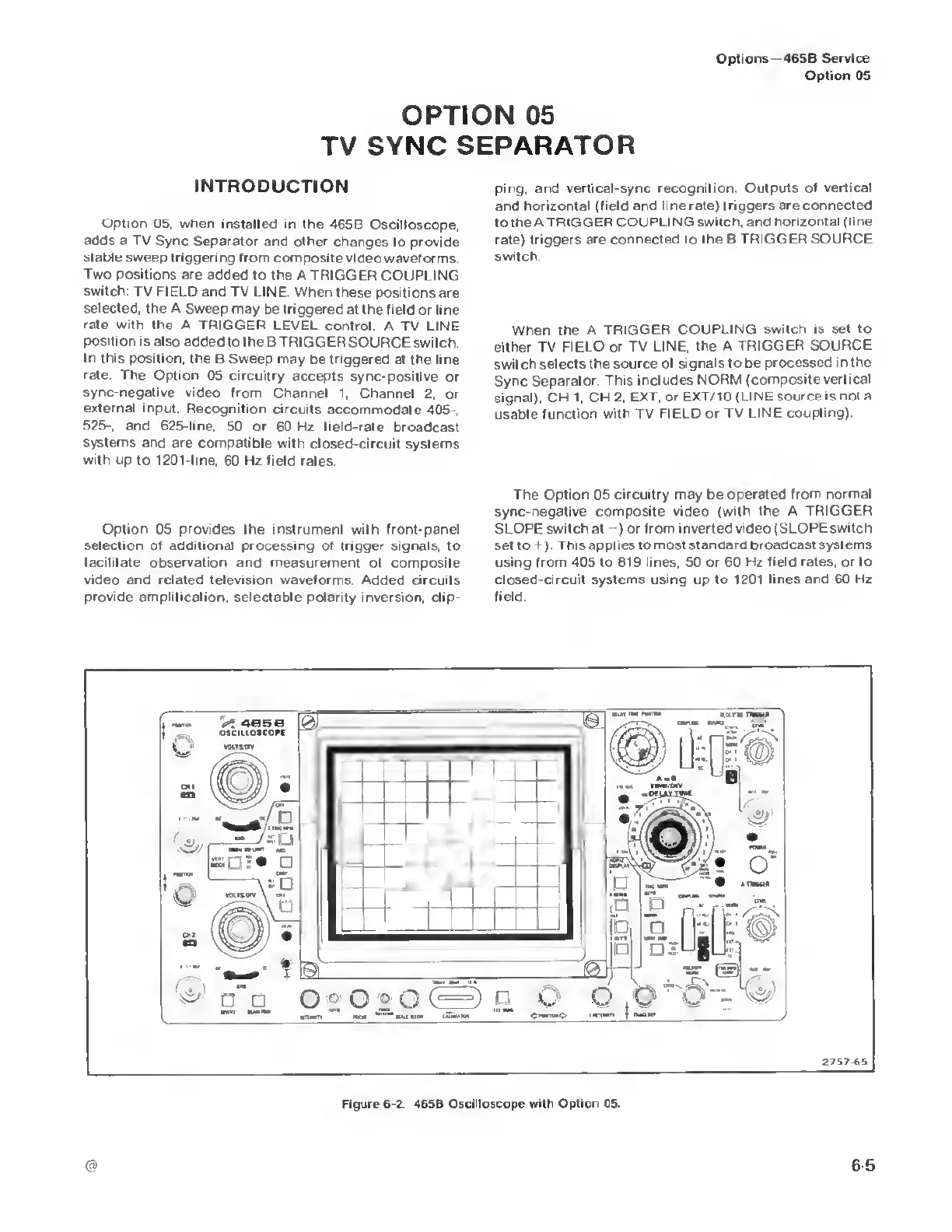
Figure 6-2. 465B Oscilloscope with Option 05.
65

 Loading...


