Theory of
Operation—465B Service
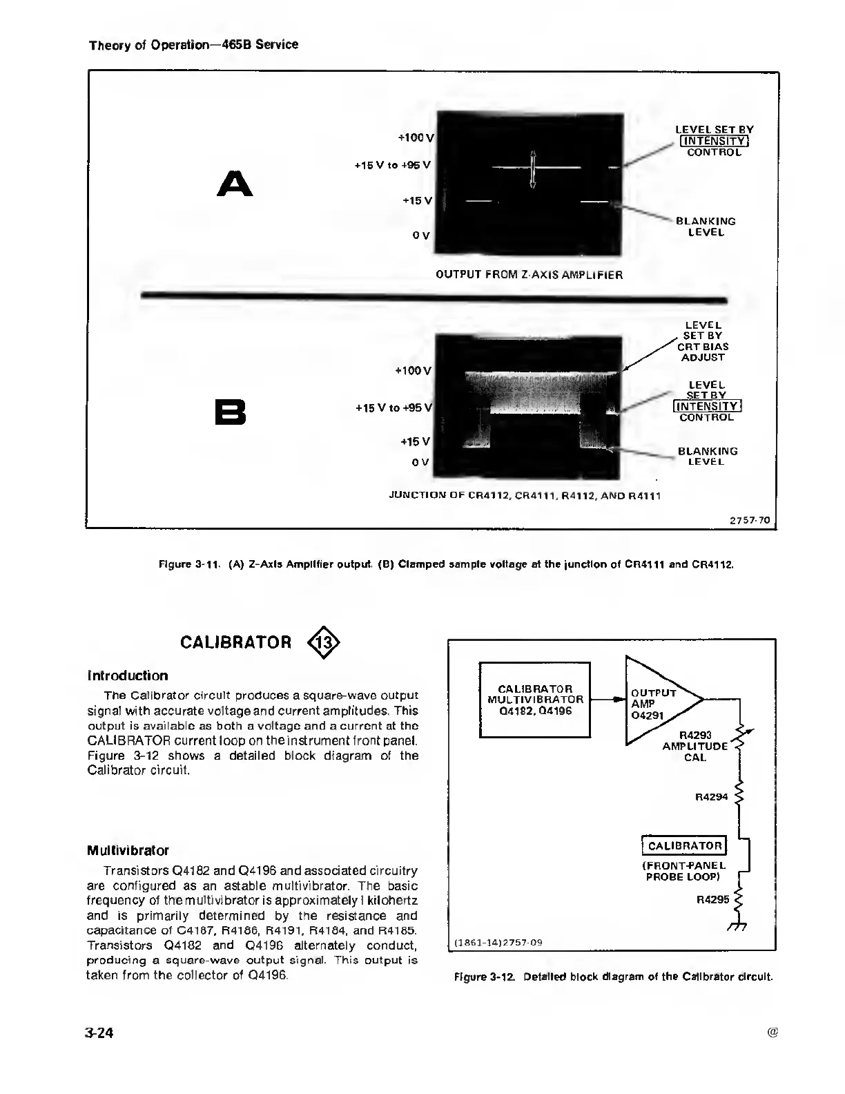
OUTPUT FROM Z-AXIS
AMPLIFIER
+100
V
+15
V to
+95
V
+15
V
0 V
LEVEL
SET BY
CRT
BIAS
ADJUST
LEVEL
SET BY
I
intensity!
CONTROL
BLANKING
LEVEL
JUNCTION
OF CR4112, CR4111,
R4112, AND R4111
2757-70
Figure 3-11. (A) Z-Axis Amplifier output.
(8)
Clamped sampie voltage at the junction
of
CR4111
and CR4112.
CALIBRATOR
Introduction
The Calibrator circuit produces a square-wave output
signal
with accurate voltage and
current amplitudes. This
output is available
as
both
a
voltage and
a
current at the
CALIBRATOR current loop on the instrument front panel.
Figure
3-12
shows a detailed block diagram of the
Calibrator circuit.
Multivibrator
Transistors Q4182 and Q4196 and associated circuitry
are configured as an astable multivibrator. The basic
frequency of the multivibrator
is
approximately I kilohertz
and
is
primarily determined
by
the resistance and
capacitance of C4187, R4186, R4191, R4184, and
R4185.
Transistors Q4182 and Q4196 alternately conduct,
producing a square-wave output signal. This output is
taken from the collector
of
Q4196.
Figure
3-12.
Detailed block diagram of the Calibrator circuit.
3-24

 Loading...


