Theory of
Operation—465B Service
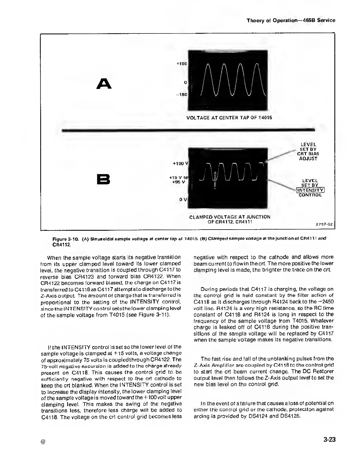
VOLTAGE AT CENTER
TAP
OF T4015
LEVEL
SET BY
CRT BIAS
ADJUST
LEVEL
SELBY
[Intensity]
control
CLAMPED
VOLTAGE AT JUNCTION
OF CR4112. CR4111
2757-12
Figure 3-10. (A)
Sinusoidal sample voltage at center tap ot
T4015. (B) Clamped sample
voltage at the Junction ot
CR4111 and
CR4112.
When the sample
voltage
starts
its
negative
transition
from its upper clamped
level toward its
lower clamped
level, the negative
transition is
coupled through C41
17 to
reverse
bias CR4123
and
forward bias CR4122.
When
CR4122
becomes forward biased,
the charge
on
C4117
is
transferred to C41 1 8
as
C41 1
7 attem pts
to
discharge
to
the
Z-Axis
output. The
amount of
charge that is
transferred is
proportional to
the
setting
of
the
INTENSITY control,
si nee the
I NTENSITY control
sets the lower
clamping level
of
the
sample voltage
from
T4015
(see Figure
3-11).
If the
INTENSITY
control is set so the
lower level of the
sample
voltage is clamped
at +15 volts, a
voltage
change
of
approximately
75
volts is coupled
through CR4122. The
75-volt negative
excursion is added
to the
charge already
present
on
C4118.
This
causes the
control grid to be
sufficiently
negative with
respect to the ert
cathode to
keep
the ert blanked.
When the
I NTENSITY
control is set
to
increase the display
intensity, the
lower
clamping level
of the
sample voltage is
movedtowardthe+IOOvolt
upper
clamping
level.
This makes the swing
of the negative
transitions
less,
therefore less charge
will
be
added to
C4118.
The
voltage on the
ert control grid
becomes less
negative with respect to
the cathode and allows more
beam current to flow in the ert.
The more positive the lower
clamping level is made, the brighter the
trace on the ert.
During periods
that
C4117
is charging, the
voltage on
the
control grid is held constant by the
filter action of
C4118
as it discharges
through R4124 back to the
-2450
volt line. R4124 is a
very high resistance, so the
RC time
constant of C4118
and R4124 is long in respect
to the
frequency of the sample voltage
from T4015. Whatever
charge is leaked off of C4118
during the positive tran-
sitions of the
sample voltage will be replaced by C4117
when the sample
voltage
makes
its negative transitions.
The fast rise and
fall
of the
unblanking pulses from the
Z-Axis Amplifier arc
coupled
by C41
18 to the control grid
to
start the ert beam current
change. The DC Restorer
output
level then follows the Z-Axis output
level
to
set the
new bias level on the
control grid.
In the event of a failure that causes a
loss of potential on
either the
control grid or the cathode,
protection against
arcing
is
provided by DS4124
and DS4125.
@
3-23

 Loading...


