Section
3
—4G5B
Service
THEORY
OF
OPERATION
INTRODUCTION
SECTION
ORGANIZATION
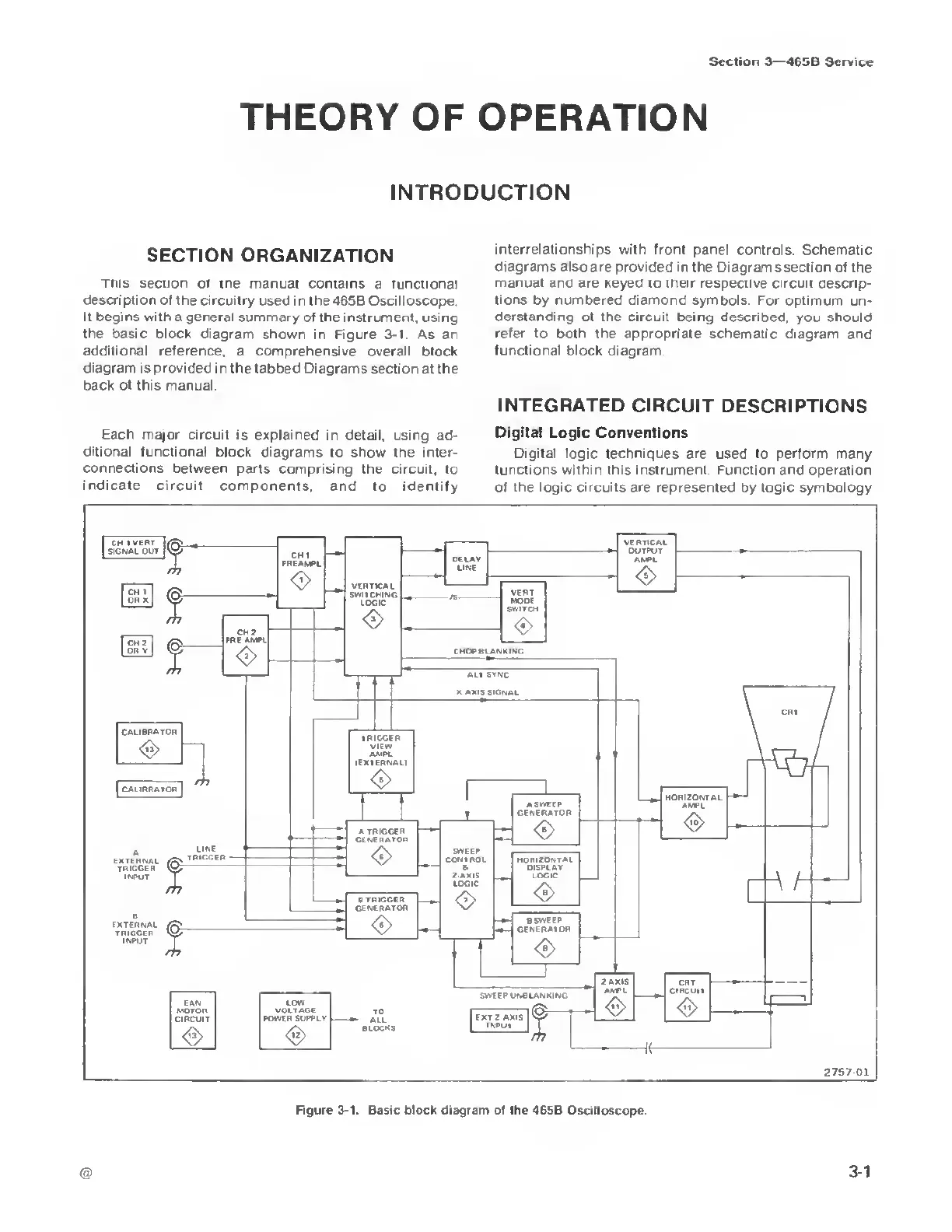
This
section ot the manual contains
a functional
description of the circuitry
used in the 465B Oscilloscope.
It begins with
a general summary of the instrument, using
the basic block
diagram shown in Figure
3-1
As an
additional reference,
a comprehensive overall block
diagram is provided
in
the
tabbed Diagrams section at the
back of this manual.
interrelationships
with front panel controls. Schematic
diagrams also are provided in the Diagrams section
of the
manual and are keyed to their
respective circuit descrip-
tions by numbered diamond symbols. For
optimum un-
derstanding of the
circuit
being
described, you should
refer to both the appropriate schematic diagram
and
functional block diagram
INTEGRATED CIRCUIT
DESCRIPTIONS
Each major
circuit is explained
in
detail, using
ad-
ditional functional
block diagrams to show the inter-
connections
between parts comprising the
circuit, to
indicate circuit
components, and
to identify
Digital Logic
Conventions
Digital logic
techniques are used to perform many
functions within this instrument Function and operation
of the logic circuits are represented by logic symbology
2757
01
Figure
3-1.
Basic block diagram ol the
465B Oscilloscope

 Loading...


