Maintenance—465B Service
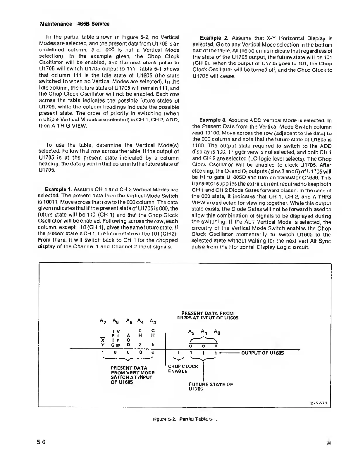
in the partial tapie shown in
Figure 5-2, no Vertical
Modes are selected, and the
present data from
U1 705
is
an
undefined column,
(i.e., 000 is not a Vertical Mode
selection). In the example given,
the Chop Clock
Oscillator
will be
enabled,
and the next
clock pulse to
U1705
will
switch U1705 output
to
111.
Table
5-1
shows
that column 111
is the
idle
state
of U1605 (the state
switched
to when no Vertical Modes
are
selected).
In the
Idle column, the future state
of U1705 will remain
111,
and
the Chop Clock Oscillator will not
be
enabled.
Each row
across the table indicates
the possible future states
of
U1705, while the
column headings indicate the possible
present
state. The order of priority in switching
(when
multiple Vertical Modes are selected)
is CH
1,
CH
2,
ADD,
then A TRIG VIEW.
To
use the table, determine the
Vertical Mode(s)
selected. Follow that row
across the table.
If the output of
U1705 is at the present
state
indicated
by
a column
heading, the
data given in that column Is the
future state of
U1705.
Example 1. Assume CH 1 and CH
2
Vertical Modes
are
selected. The present data from the
Vertical Mode Switch
is
10011. Move acrossthatrowtothe
000 column. The data
given
indicates that if the present
state of U1705 is
000,
the
future state will
be 110
(CH
1)
and that the Chop Clock
Oscillator
will be enabled. Following
across the
row,
each
column, except
110 (CH
1),
gives
the same future
state. If
the present state is CH
1,
thefuturestate
will belOl (CH2).
From there,
it will switch back to CH 1
for the chopped
display of the Channel 1 and Channel
2 input signals.
Example
2. Assume that X-Y
Horizontal Display
is
selected.
Go to any Vertical Mode
selection
in the bottom
half of the table. All
the columns
indicate that regardless
of
the
state of the U1705 output, the
future state will
be
101
(CH
2).
When the output
of U1705 goes to
101,
the Chop
Clock Oscillator
will be turned
off, and the Chop Clock to
U1705
will cease.
Example
3. Assume ADD
Vertical Mode is selected.
In
the
Present Data from
the Vertical Mode
Switch column
read 10100. Move
across the row
(adjacent to the data)
to
the
000
column
and
note that the future state
of
U1605
is
1100. The output
state required to switch
to the ADD
display
is 100. Trigger view
is not selected,
and both CH 1
and CH
2
are
selected
(LO logic level selects).
The Chop
Clock Oscillator
will
be
enabled
to clock
U1705. After
clocking,
the
Q
0
and
Q, outputs (pins 3 and
6)
of U1705 will
be HI to gate
U1805D and turn on transistor
Q1636. This
transistor
supplies the
extra current required
to keep both
CH 1 and CH 2 Diode
Gates forward biased.
In the case of
the
000 state, it indicates that
CH
1,
CH
2,
and A TRIG
VIEW
are
selected
for viewing
together. While
this output
state
exists,
the Diode
Gates will not
be
forward biased
to
allow this combination
of signals
to be displayed during
the switching. If the ALT
Vertical Mode
is selected, the
circuitry of the Vertical
Mode Switch enables
the Chop
Clock Oscillator
momentarily to
switch
U1605
to the
selected
state without
waiting for the next Vert Alt
Sync
pulse from
the Horizontal Display
Logic circuit.
A
5
A
4
PRESENT
DATA FROM
U1705 AT
INPUT
OF U1605
X
Y
T
V
R
I
I
E
G
W
A
D
D
C
H
C
H
PRESENT DATA
FROM VERT MODE
SWITCH AT INPUT
OFU1605
CHOP CLOCK
ENABLE
OUTPUT OF
U1605
FUTURE STATE
OF
U1706
2757-73
Figure
5-2. Partial Tabia
5-1.
56

 Loading...


