Theory of Operation—
465B Service
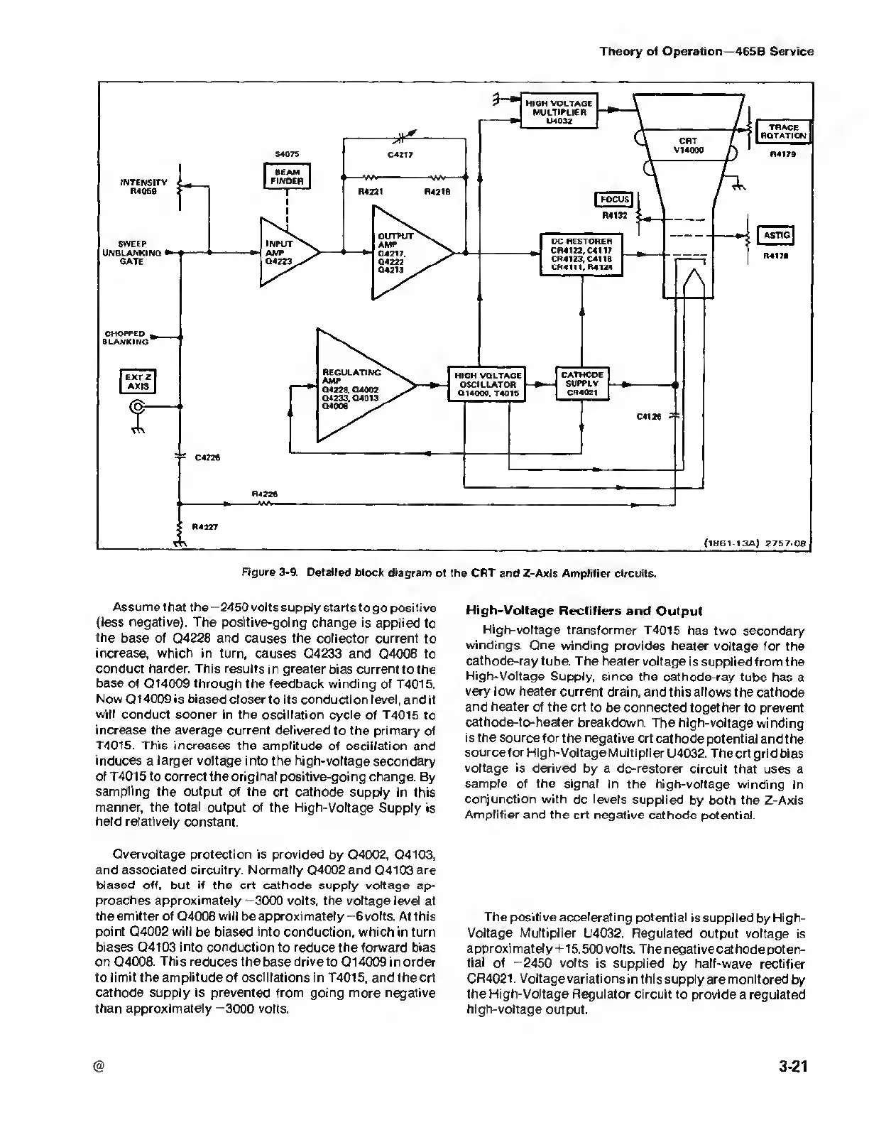
Figure
3-9-
Detailed block
diagram
of
the
CRT and Z-Axis Amplifier circuits.
Assume
that the
—2450
volts supply starts
to go positive
(less negative). The
positive-going change is
applied to
the
base of Q4228 and causes the collector current
to
increase, which
in turn, causes Q4233 and Q4008 to
conduct harder. This results
in
greater
bias current to
the
base of Q14009 through the feedback
winding of T4015.
Now Q1
4009 is biased closer to its conduction
level, and it
will conduct sooner in the
oscillation cycle of T4015 to
increase the average
current delivered to the primary of
T4015. This increases the amplitude
of
oscillation
and
induces
a
larger
voltage into the high-voltage
secondary
of T4015 to correct the original positive-going change.
By
sampling the output
of the crt cathode supply in this
manner, the total output
of the High-Voltage Supply is
held
relatively constant.
Overvoltage protection is provided
by Q4002, Q4103,
and associated circuitry. Normally
Q4002 and Q4103 are
biased off, but if the crt cathode supply voltage
ap-
proaches approximately
-3000
volts, the voltage level
at
the emitter
of Q4008
will
be
approximately
-6
volts. At this
point
04002
will
be biased
into
conduction, which in turn
biases Q4103 into conduction to reduce
the forward bias
on Q4008. This reduces the base drive to
Q
1 4009 in order
to limit the amplitude
of
oscillations in T4015, and
the crt
cathode supply is
prevented from
going
more negative
than approximately
-3000
volts.
High-Voltage Rectifiers
and Output
High-voltage transformer T4015
has
two
secondary
windings. One winding provides heater
voltage for the
cathode-ray
tube. The heater voltage
is supplied from
the
High-Voltage Supply, since
the cathode-ray
tube has a
very low heater current drain,
and this allows
the cathode
and heater
of the crt
to be connected together to
prevent
cathode-to-heater
breakdown. The high-voltage
winding
is the
source for the negative crt
cathode potential and the
source for High-Voltage
Multiplier
U4032.
The crt
grid bias
voltage is derived
by a dc-restorer circuit that
uses a
sample of
the signal in the
high-voltage winding in
conjunction
with dc levels
supplied by both the Z-Axis
Amplifier and the
crt negative cathode potential.
The positive accelerating
potential is supplied
by
High-
Voltage Multiplier
U4032. Regulated output
voltage is
approximately
+15.500 volts. The negative cathode
poten-
tial
of
-
2450 volts is supplied
by
half-wave
rectifier
CR4021. Voltage
variations in this supply are monitored
by
the High-Voltage Regulator
circuit to provide a regulated
high-voltage
output.
@
3-21

 Loading...


