Calibration Procedure—465B
Service
Performance Check
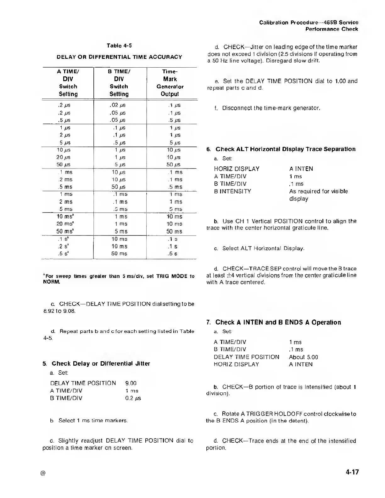
Table
4-5
DELAY OR DIFFERENTIAL TIME
ACCURACY
A TIME/ B TIME/ Time-
DIV DIV Mark
Switch Switch Generator
Setting Setting Output
.2 fjs
.02 /JS
.1
/JS
.2//S .05
/js .1
/JS
.5
u
s .05 /zs
.5
/js
1
/JS
.1
/JS
1
us
2 /zs
.1
/JS
1
/JS
5
/zs
.5
/js
5
/js
10
a/s 1
/JS
10
£IS
20
/zs
1
/JS 10/zs
50 fjs 5
/
JS
50
/is
.1 ms
10 /js .1
ms
.2 ms
\0/js .1
ms
.5 ms
50
/is
.5 ms
1
ms
.1 ms 1 ms
2
ms
.1 ms
1
ms
5
ms .5 ms
5 ms
10 ms*
1
ms
10 ms
20 ms* 1 ms 10 ms
50 ms* 5 ms 50 ms
.1 s* 10 ms .1
s
.2 s* 10 ms .1
s
.5 s* 50 ms .5 s
d.
CHECK—Jitter on leading edge of the time marker
does
not
exceed
1 division
(2.5
divisions if operating from
a 50 Hz line voltage). Disregard slow drift.
e.
Set the DELAY TIME POSITION dial to 1.00 and
repeat parts c and d.
f.
Disconnect
the
time-mark generator.
6. Check ALT
Horizontal Display Trace Separation
a. Set:
HORIZ DISPLAY
A TIME/DIV
B
TIME/DIV
B
INTENSITY
A INTEN
1 ms
.1 ms
As required for visible
display
b. Use
CH 1 Vertical POSITION control to align the
trace with the center horizontal graticule line.
c. Select ALT Horizontal Display.
“For sweep
times greater than 5ms/div, set TRIG
MODE to
NORM.
d.
CHECK—TRACE SEP control will move the B
trace
at least ±4
vertical divisions
from the
center graticule line
with A trace centered.
c.
CHECK—DELAY TIME POSITION dial setting to
be
8.92 to 9.08.
d.
Repeat parts
b and cfor each
setting listed in Table
4-5.
5.
Check Delay or Differential Jitter
a. Set:
DELAY TIME POSITION 9.00
A TIME/DIV 1 ms
B
TIME/DIV
0.2 /is
b
Select 1 ms time markers
c.
Slightly readjust DELAY TIME POSITION dial to
position a time marker on screen.
7. Check A INTEN and B ENDS A Operation
a.
Set:
A TIME/DIV
1 ms
B TIME/DIV ,1ms
DELAY TIME POSITION
About 5.00
HORIZ DISPLAY
A
INTEN
b. CHECK—
B
portion of
trace
is
intensified (about 1
division).
c.
Rotate
A TRIGGER HOLDOFF control clockwise
to
the B
ENDS A
position (in the detent).
d. CHECK—Trace ends at the end of the intensified
portion.

 Loading...


