Calibration
Procedure—
465B Service
Adjustment
Procedure
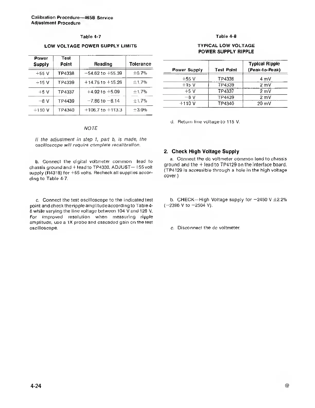
Table
4-7
LOW VOLTAGE POWER
SUPPLY LIMITS
Power
Supply
Test
Point Reading
Tolerance
+55 V TP4338
-54.62 to +55.39 ±0.7%
+15 V
TP4339 +14.75 to
+15.26 ±1.7%
+5
V
TP4337
+4.92
to
+5.09 ±1.7%
-8
V
TP4439
-7.86
to
-8.14
±1.7%
+110 V
TP4340
+106.7
to
+113.3 ±3.0%
NOTE
II the
adjustment in step
1,
part b, is
made,
the
oscilloscope will require complete
recalibration.
b.
Connect the
digital voltmeter common lead to
chassis
ground and +
lead
to TP4338.
ADJUST—+55 volt
supply (R4318) for
+55
volts.
Recheck all supplies accor-
ding to
Table
4-7.
c.
Connect the test oscilloscope to the indicated test
point and
checkthe ripple amplitude according to Table
4-
8
while varying the line voltage
between
104 V and 126 V.
For improved
resolution when measuring ripple
amplitude,
use a
IX probe and cascaded gam on the test
oscilloscope.
Table
4-8
TYPICAL LOW VOLTAGE
POWER SUPPLY RIPPLE
Power Supply Test Point
Typical Ripple
(Peak-to-Peak)
+55 V TP4338 4 mV
+15
V
TP4339
2
mV
+5 V TP4337
2
mV
-8
V
TP4439 2
mV
+110
V
TP4340
20 mV
d. Return line voltage to 115 V.
2. Check High Voltage Supply
a.
Connect the
dc
voltmeter common lead to chassis
ground and the + lead
to
TP4129 on the interface board.
(TP4129 is accessible through a hole in the high voltage
cover.)
b. CHECK—
High
Voltage
supply for
-2450
V ±2.2%
(-2396
V to
-2504
V).
c.
Disconnect the
dc
voltmeter.

 Loading...


