Table
1-1
-
--
-
-
--
-
--
-
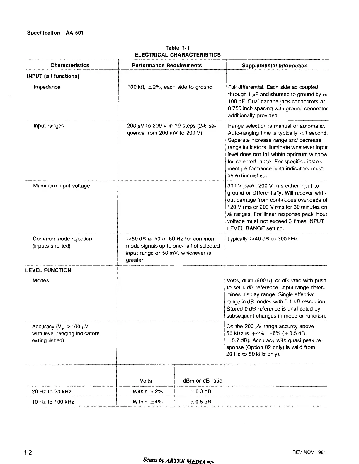
ELECTRICAL CHARACTERISTICS
7-
--
-
-
r
-
-
Characteristics
.-
-
-
--
-
-
--
-
-
-.
-
-
INPUT (all functions)
Impedance
----
-
.
-
-
-
Maximum Input voltage
-
--
-
Common mode rejection
(inputs shorted)
-
-
--
- -
LEVEL FUNCTION
Modes
-
--
Accuracy (V,,
a
100 pV
with level ranging indicators
extinguished)
-
-
---
20
Hz
to 20
kHz
Performance Requirements
--
Supplemental Information
.
--
-
-.
-
--
--
--
-
,
100
kR,
+
2%, each side to ground
200
pV to 200 V in 10 steps (2-6 se-
quence from 200
mV to 200 V)
--
~
---
~-
--
--
250 dB at 50 or 60
Hz
for common
mode signals up to one-half of selected
input range or 50
mV, whichever is
greater.
--
-
-
Volts
I
I
Full differential. Each side ac coupled
through
1
pF
and shunted to ground by
=
100 pF. Dual banana jack connectors at
0.750 inch spacing with ground connector
additionally provided.
-
-.
-
Range selection is manual or automatic.
Auto-ranging time is typically
(1
second.
Separate increase range and decrease
range indicators illuminate whenever input
level does not fall within optimum window
for selected range. For specified instru-
ment performance both indicators must
be extinguished.
-
-
--
.
.
-.
300
V
peak, 200 V rms either input to
ground or differentially. Will recover with-
out damage from continuous overloads of
120
V
rms or 200
V
rms for 30 minutes on
all ranges. For linear response peak input
voltage must not exceed 3 times INPUT
LEVEL RANGE setting.
~~
~~
~
Typically 240 dB to 300
kHz.
(
Volts, dBm (600
0).
or dB ratio with push
Within
+
2%
1
-
REV
NOV
1981
to set 0 dB reference. lnput range deter-
mines display range. Single effective
range in dB modes with 0.1 dB resolution.
Stored
0 dB reference is unaffected by
subsequent changes in mode or function.
-.
On the 200 pV range accurcy above
50
kHz
is +4%, -6% (+0.5 dB,
-0.7 dB). Accuracy with quasi-peak re-
sponse (Option 02 only) is valid from
20
Hz
to 50
kHz
only).
 Loading...


