Theory of Operation-AA 501
Table 3-1
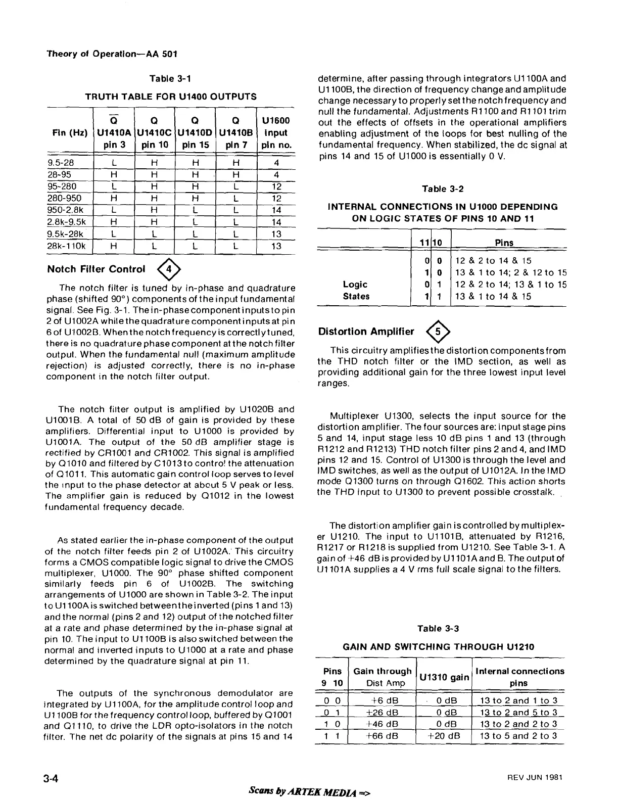
TRUTH TABLE FOR
U1400 OUTPUTS
Notch Filter Control
@
Fln (Hz)
-
9.5-28
28-95
95-280
280-950
950-2.8k
The notch filter is tuned by in-phase and quadrature
phase (shifted
90") components of the input fundamental
signal. See Fig.
3-1. Thein-phasecomponent inputsto pin
2 of
U1002A while thequadrature component inputsat pin
6
of UI002B. Whenthe notch frequency is correct1 y tuned,
there is no quadrature phasecomponent at the notch filter
output. When the fundamental null (maximum amplitude
rejection) is adjusted correctly, there is no in-phase
component in the notch filter output.
The notch filter output is amplified by
U1020B and
U1001B. A total of 50 dB of gain is provided by these
amplifiers. Differential input to
U1000 is provided by
U1001A. The output of the 50 dB amplifier stage is
rectified by
CR1001 and CR1002. This signal is amplified
by 01010 and filtered by
C1013to contro! the attenuation
of 0101 1. This automatic gain control loop serves to level
the
Input to the phase detector at about 5
V
peak or less.
The amplifier gain is reduced by 01012 in the lowest
fundamental frequency decade.
-
Q
U1410A
pin 3
L
H
L
H
L
As
stated earlier the in-phase component of the output
of the notch filter feeds pin 2 of
U1002A:This circuitry
forms a CMOS compatible logic signal to drive the CMOS
multiplexer,
U1000. The 90" phase shifted component
similarly feeds pin 6 of
U1002B. The switching
arrangements of
U1000 are shown in Table 3-2. The input
toU1100Aisswitched betweentheinverted (pins 1 and 13)
and the normal (pins 2 and 12) output of the notched filter
at a rate and phase determined by the in-phase signal at
pin 10. The input to
U1100B is also switched between the
normal and inverted inputs to UlOOO at a rate and phase
determined by the quadrature signal at pin 11.
The outputs of the synchronous demodulator are
integrated by
UllOOA, for the amplitude control loop and
U1100B for the frequency control loop, buffered by 01001
and
01 110, to drive the LDR opto-isolators in the notch
filter. The net dc polarity of the signals at pins 15 and 14
Q
U1410C
pin 10
H
H
H
H
H
determine, after passing through integrators U1100A and
U1 1008, the direction of frequency change and amplitude
change necessary to properly set the notch frequency and
null the fundamental. Adjustments
R1100 and R1101 trim
out the effects of offsets in the operational amplifiers
enabling adjustment of the loops for best nulling of the
fundamental frequency. When stabilized, the dc signal at
pins 14 and 15 of
U1000 is essentially 0
V.
Table 3-2
Q
U1410D
pin 15
H
H.
H
H
L
INTERNAL CONNECTIONS IN UlOOO DEPENDING
ON LOGIC STATES OF
PINS 10 AND 11
I
I
1
Logic
States
Q
U1410B
pin
7
H
H
L
L
L
Pins
12
&
2
to 14; 13
&
1 to 15
13
&
1 to 14
&
15
U1600
input
pln no.
4
4
12
12
14
Distortion Ampllfier
0
This circuitry amplifies the distortion components from
the THD notch filter or the IMD section, as well as
providing additional gain for the three lowest input level
ranges.
Multiplexer
U1300, selects the input source for the
distortion amplifier. The four sources are: input stage pins
5
and 14, input stage less 10 dB pins 1 and 13 (through
R1212 and R1213) THD notch filter pins 2 and
4,
and IMD
pins 12 and 15. Control of U1300 is through the level and
IMD switches, as well as the output of
U1012A. In the IMD
mode 01300 turns on through 01602. This action shorts
the THD input to
U1300 to prevent possible crosstalk.
The distortion amplifier gain iscontrolled by multiplex-
er
U1210. The input to UllOlB, attenuated by R1216,
R1217 or R1218 is supplied from U1210. See Table 3-1. A
gain of
+46 dB is provided by U1101Aand B. The output of
UllOlA supplies a 4
V
rms full scale signal to the filters.
Table
3-3
GAIN AND SWITCHING THROUGH U1210
REV
JUN
1981
Scans
by
ARTEK
MEDLQ
+
Pins
9
10
0 0
0
1
10
11
Gain through
Dist Amp
$6
dB
f26 dB
+46 dB
+66
dB
U1310 gain
0 dB
0 dB
0 dB
+20 dB
Internal connections
pins
13 to 2 and 1 to 3
13 to 2 and 5 to 3
13 to 2 and 2 to 3
13 to
5
and 2 to 3
 Loading...


